After doing a search on 'Star Ground methods' and 'Star ground techniques' I think I understand, but felt that in the interest of safety and future troubleshooting, I would ask for clarification. Any help is appreciated.
1) Some of the responses seemed to be somewhat contradictory, but I understand that the signal ground is not considered the same as the safety ground. However, I noted a few responses that indicate the safety ground and star ground may need to be connected via a low ohm resistor, or a power thermistor. What situations are likely to be encountered where it is not the best practice to use this method? It seems that during a failure mode, all grounds should be in some way connected to minimize end user risk.
2) Is there a general rule of thumb as to lead lengths on a star ground's connection cable? It seems an endless series of compromises. It seems that the star ground should be some distance away from the PSU filter capacitor connection, due to large current swings. Should it be located closer to other signal grounds in the circuit? My current train of thought has the PSU caps running to a 6" 16awg wire with a ring terminal on the end as its star ground point. I then thought I should connect other signal grounds to similar 3" wires with rings and connect these all at one point. Is this an accepted technique?
3) Does the 'mass' of the star ground have any effect? By this, I mean would it be prudent to connect the star ground to, say, a 1" X 1" X 1/2" piece of copper and insulate this from the chassis. Then connect the chassis (and safety) ground to the copper bar via a resistor or thermistor. Does this have any theoretical effect and is this worth effort in practical implementation?
My specific current application is a variable power supply to help in testing my future amps. My scheme would result in a variable +, variable - and a 0V reference, which would be referenced to the safety ground via a resistor.
If anyone has additional suggestions or clarifications, I would appreciate it. I am attempting an intelligent layout as well, minimizing interference from the torroid, filter caps etc, but without knowing some good general rules as to the application, wire lengths etc for the star ground concept, I do not know the most appropriate compromises to make.
Thanks for the help. Excellent forum!
Sandy.
Hi Sandy,
Let's step back a little. A star ground is a consequence of something else and it is not uncommon to have several star grounds within a single unit.
Let me explain. Current flows in loops (at these frequencies). It is important to identify these loops. Sometimes two or more current loops end up sharing the same wire. This may or may not be important - it depends whether any of the associated circuits care about the voltage drop along the wire. Because the voltage drop will be proportional to the sum of the current loops. A star ground point is just a way to prevent one or more current loops sharing the same wire.
Have a think about this, hopefully all will become clear.
So the physical size of a star point and its proximity to psu capacitors is not important per se. The total length of psu leads may be important, especially as it increases the area enclosed by current loops which causes high loop inductance. The inductance a circuit sees is related to the physical area enclosed by the circuit. This is why you often seen psu supply and return cables closely bound together with cable ties: it isn't just for tidiness.
As you are designing a psu for amp testing you may want to consider whether you want a psu str point at the psu itself or not. You will be forecing this unless your +'ve and -'ve supplies are totally separate with separate grounds. If you make the supply in the latter manner you have the choice.
I'm not familiar with all countries safety codes wrt mains earthing of equipment. However, I believe if a piece of equipment has a conductive case then the case must be connected to mains earth. This is not the case, for example, with mobile phones and laptop PCs as everything is made of plastic and the mains is isolated by a plug transformer. Provided the equipment case is earthed, it is not essential to connect signal ground to mains earth. Indeed, it is normal practice to connect signal ground to earth at a single point - say at the CD player or the amp or the turntable but no more than once. If there are multiple connections this can create noise.
There is a whole thread about this somewhere in this forum.
Getting There
traderbam,
Thanks for the reply. I have a working understanding of the need to keep the current flows in different wires, hence the star scheme. You also confirmed that the size of the star ground isn't a factor.
You did raise another question, though. How would the +'ve and -'ve be totally isolated from each other, without sharing a common ground? My torroid has a total of 8 wires. I was planning on running the mains wires in parallel and running the output wires in series, making the end arrangement +,0,-. I could not do this without referencing both windings to each other, if I understand correctly. Are you suggesting an alternative arrangement and if so, what benefits would be likely? Would this result in the 0V ref simply being ignored throughout the supply?
For reference, I am using the Elliot variable lab supply schematic.
Thanks for the response.
Sandy.
jam said:Another Charlottean, nothing is sacred anymore!
Hi Sandy,
Welcome to the forum. I will have to search but I might be able to find some notes for you.
Jam
I actually tried to send an e-mail to you a few weeks ago, using the forum link, but it didn't work. I'm an electronics neophyte, but can hold my own with metal construction etc. Thought I'd offer some shop time etc, if you could use the resources.
Let me know.
S.
What I am suggesting only works if your transformer has dual secondary windings. If so, make two identical psus off each secondary. Then you can connect these in series at the psu terminals or not as the need arises. This makes a more flexible psu for amp testing because it means you don't need to make the psu terminals the star point if you don't want to.
For example, if you are powering an amps psu directly (bypassing its own transformer/rect) and you want to keep the amps existing star point as the only star point.
The two independent supplies float thanks to the isolation of the transformer and you can connect them up in series and choose which terminal is 0V as you like. For example, if each psu is 12V, you can make -12,0,+12 or you can make 0,+24 or 0,-24.
Click!
OK, that makes sense (without looking at a specific schematic). It seems to be all in where you link up the star ground, inside of the PS for the center tapped variety, to ensure that the reference point is correct and the voltage regulators are at the same ground potential. With 2 separate windings, there is no reference from one supply to another and the reference of 0V is established when you connect the items in series.
Thanks. It seems obvious now from your first post. . .
Sandy.
Stupid question
Is it possible to attain a signal ground without the isolation provided by the transformer? Let us say I am willing to work with high voltage transistors, and provide an insulated container - can I put a bridge directly on mains to get DC for circuit operation and still make the signal in and signal out a safe operation? Probably not!traderbam said:The two independent supplies float thanks to the isolation of the transformer and you can connect them up in series and choose which terminal is 0V as you like.


")
Re: Stupid question
 The simple answer is no, it would not be safe under any circumstances!
But I have to ask the question, why would you want to do this anyway?
jag said:
Is it possible to attain a signal ground without the isolation provided by the transformer? Let us say I am willing to work with high voltage transistors, and provide an insulated container - can I put a bridge directly on mains to get DC for circuit operation and still make the signal in and signal out a safe operation? Probably not!
The simple answer is no, it would not be safe under any circumstances! But I have to ask the question, why would you want to do this anyway?
Re: Re: Stupid question
Not trying to do it, just a theoritical question...pinkmouse said:But I have to ask the question, why would you want to do this anyway?
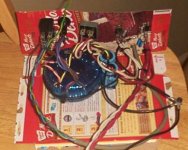
Current Status (PIC)
As of tonight, I have successfully tested the lab supply. Thanks for the help thus far.
The next phase is finalizing the component layout so I can begin the chassis fabrication. The current wiring is subject to change, pending suggestions for an improved layout.
The following pic, plus those available at the link, are indeed the proposed layout put together on a cake box. I figure a few laughs are in order.
Anyway, any comments on improving the physical layout, such as relocating capacitors, re-routing wiring or moving this or that would be appreciated.
Thanks for the continuing help.
S.
PS: The high res pictures are on my site at:
http://tshouston.net/labsupply/thumbs/labsuppl.htm
. . . not wanting to waste DIYA's bandwidth!
Attachments
traderbam said:Provided the equipment case is earthed, it is not essential to connect signal ground to mains earth. Indeed, it is normal practice to connect signal ground to earth at a single point - say at the CD player or the amp or the turntable but no more than once. If there are multiple connections this can create noise.
Very instructive thread. This is what I wanted.
So, do you mean that I don't need to connect the signal grounds to the star point once they are connected to the conductive (and earthed) enclosure?
Jazz,
So these things are done differently by different people.
The way to avoid earth loop noise is to connect mains earth to the signal ground at a single point. In other words, either in your CD, your pre-amp or your power amp, but not more than once.
For health and safety reasons all boxes that have mains entering them must have all their chassis metalwork connected to mains earth.
Some people will use a small resistor, sub 100-ohms, to tie the signal ground to mains earth within all boxes to stop the signal ground floating too far from mains earth. The resistance is high enough to avoid earth loop noise. But this is optional.
Try searching this site for more details on causes and cures of earth loop noise. I think there is a lot of commentary already.
Re: Stupid question
Hi Jag,
Yes you can. Try this site and chose circuit #13
http://www.mitedu.freeserve.co.uk/Circuits/Power/power.html
pf
jag said:
Is it possible to attain a signal ground without the isolation provided by the transformer? Let us say I am willing to work with high voltage transistors, and provide an insulated container - can I put a bridge directly on mains to get DC for circuit operation and still make the signal in and signal out a safe operation? Probably not!
Hi Jag,
Yes you can. Try this site and chose circuit #13
http://www.mitedu.freeserve.co.uk/Circuits/Power/power.html
pf
- Status
- This old topic is closed. If you want to reopen this topic, contact a moderator using the "Report Post" button.
- Home
- Amplifiers
- Solid State
- Star Ground methods