I am taking a Yamaha M-45 and replacing the amp section with
Aussie Amp NX series modules. I am going to continue to use
the front 'power' meters; attached are the pictures of the 'schematic'
of the meter circuit for the Yamaha M-45.
Power Supply and meter lights. The main transformer has a second
set of secondaries. . .that is what runs the meter and panel lights.
Attachments
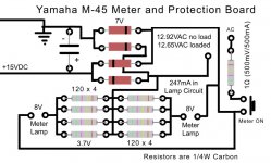
Yamaha M-45 main meter circuit. Input is from amplifier output section.
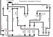
The transistor C2240 is switched via the protection circuit and opens
the connection for the meter circuit to become active.
I want to take C2240 out of the circuit and replace with a jumper between
ce since the protection circuit is no longer in the amplifer. With
no power to the protection board, there is no +V on the base of
C2240 to allow the meter board to turn on.
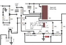
I was thinking of testing with a 10 ohm resistor first. . measure voltage
drop and calculate current. . .see if it will turn on meters. This
branch of the circuit goes to a 27Kohm resistor then the LED driver
chip.
The transistor C2240 is switched via the protection circuit and opens
the connection for the meter circuit to become active.
I want to take C2240 out of the circuit and replace with a jumper between
ce since the protection circuit is no longer in the amplifer. With
no power to the protection board, there is no +V on the base of
C2240 to allow the meter board to turn on.
I was thinking of testing with a 10 ohm resistor first. . measure voltage
drop and calculate current. . .see if it will turn on meters. This
branch of the circuit goes to a 27Kohm resistor then the LED driver
chip.
Attachments
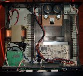
Meters now work with other amplfier. . . Removed transistor and
replaced with 15kohm resistor.
Now it is time to install other amp in shell of M-45. Also thinking of
making meters adjustable. . .low power output and high power
output. The lowest LED is 0.06W into 8ohms (0.693mV | 86.6mA).
There are other models of Yamaha M series amplifiers that have
adjustable range for the meters. . . maybe even selectable load!
[+9dB] 250W
[0dB] 125W (31.62V)
[-3dB] 63W (22.45V)
[-7dB] 25W (14.14V)
[-10dB] 12.5W (10V)
[-13dB] 6.3W (7.1V)
[-17dB] 2.5W (4.47V)
[-20dB] 1.25W (3.16V)
[-23dB] 0.63W (2.24V)
[-27dB] 0.25W (1.41V)
[-30dB] 0.13W (1.02V)
[-33dB] 0.06W (693mV)
Yamaha watt meters and dB don't match. . .250W is not +9dB of
125W! It is +3dB. . . marketing. . . "Look, our amp can output +9dB!"
Changing the meters by a factor of 10 seems reasonable. . . the
old [0dB] 125W would become [0dB] 12.5W. The input resistor
is 100K for high level input adjust and 10K for the low input adjust.
By scaling them down. . .the meter would be more sensitive to
the voltage. . .thus read lower values. It would only take 10V to
run the meter up to 125W LED instead of 31.62V.
OLD METER SETTING --> LOW POWER SETTING
[+9dB] 250W
[0dB] 125W (31.62V) --> 12.5W (10V)
[-3dB] 63W (22.45V) --> 6.3W (7.1V)
[-7dB] 25W (14.14V) --> 2.5W (4.47V)
[-10dB] 12.5W (10V) --> 1.25W (3.16V)
[-13dB] 6.3W (7.1V) --> 0.63W (2.24V)
[-17dB] 2.5W (4.47V) --> 0.25W (1.41V)
[-20dB] 1.25W (3.16V) --> 0.13W (1.02V)
[-23dB] 0.63W (2.24V) --> 0.06W (693mV)
[-27dB] 0.25W (1.41V) --> 0.025W (447mV)
[-30dB] 0.13W (1.02V) --> 0.013W (322mV)
[-33dB] 0.06W (693mV) --> 0.006W (219mV)
Hello. I was curious (given your experience with the M-45s) if you think something like this would be possible:
An externally hosted image should be here but it was not working when we last tested it.
- Status
- This old topic is closed. If you want to reopen this topic, contact a moderator using the "Report Post" button.
- Home
- Amplifiers
- Solid State
- Yamaha M-45 Power Meter Mods