Well it has been years waiting patiently in a box. the pre-amp section is crippled due to corrosion of the pots, so I've decided to be an amp only. My vintage soundcraftman as the preamp.
I rebuilt the power supply (new caps/ rectifier/ bypass caps)
Then some flashy banana plugs and phono inputs. test.. hmmm-- sweet!
I had forgotten how well this amp performs. This cute little amp has a new life.
Anyone out there know the bias setting? I used the standard 5mv across the emitter resistor or ? (note:I don't have a distortion analyzer- but a good ear and 0-scope.)
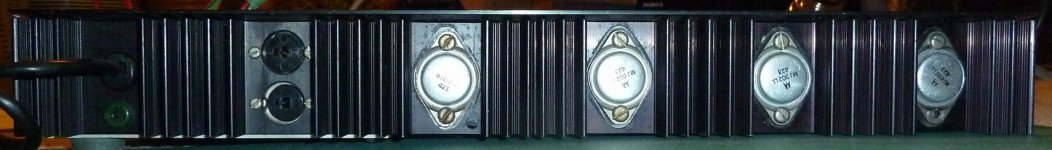
Heatsink is a bit small and disjointed (4th transistor is on a 2nd section). It runs hot (after jamming 30min) and the 4th transistor runs cooler than its complement. Anyone know what the original specs were?
I rebuilt the power supply (new caps/ rectifier/ bypass caps)
Then some flashy banana plugs and phono inputs. test.. hmmm-- sweet!
I had forgotten how well this amp performs. This cute little amp has a new life.
Anyone out there know the bias setting? I used the standard 5mv across the emitter resistor or ? (note:I don't have a distortion analyzer- but a good ear and 0-scope.)
Heatsink is a bit small and disjointed (4th transistor is on a 2nd section). It runs hot (after jamming 30min) and the 4th transistor runs cooler than its complement. Anyone know what the original specs were?
How do you know the current(which is what is the issue here) without knowing/telling the value of the resistor?
The P50 has TIP35/TIP36 output em followers,but with a little unusual arrangement of the resistors(0.15ohms).They are placed in the collectors and directly connected to + and -
I wish there was a standard using a 1ohm resistor to measure the current,and then the resistor is shorted in normal use.Would create a lot less errors,I believe.
bias never easy
I agree.
I usually measure the voltage across the emitter resistors which is much safer than pulling a fuse.
When you know that 7ma should flow through the emitter resistor, and it is 0.15 ohm ( this amp is a bit weird, with collector and emitter resistors). Run the calculation,, v=ir carry the zeros .....
I read the current by placing the multimeter on the amp output and emitter pin of the transistor, Mr. Mj802. .. but higher is not necessarily bad. Just closer to class A, but check the heat!
I'll be changing the heatsink anyway because my speakers are 4ohm.
I was once instructed to use a distortion analylizer ($$$) for a SAE amp. Don't have one. JUst tweek it and test, listen, and feel the heat. As we know, it is highly subjective. That's why it has us dIY's working so hard.
pwd
New Vintage Cambridge Audio site!!
Hello.
I've, in the past seen some requests for info on the original Cambridge Audio gear - have P50 MkII / P60 / T55 / R50 myself - not all working (...).
Just over a week back I created a Google Groups site.
At present I've donated my Cambridge Audio P50 Service Manual - 80pp - contains all the info on the 3 types of that amp - there's a P60 circuit diagram - info/reviews on these + the T55 & R50 loudspeakers.
Stan Curtis is a member too!!
Hope that the site will be useful for info - also maybe some discussion on Cambridge Audio gear!
http://groups.google.com/group/vintage-cambridge-audio
All best
Frank
Wake up the Cambridge thread.
I've just got a P60, a design classic, in lovely condition. Has anyone got one of these? I need the colours of the transformer primary, it came with the voltage selector missing. Failing that what's the best way to find the sense of the two windings?
It needs a new volume control with a mains switch, I can't find one anywhere. It's a 47K log with a flatted shaft. Any ideas?
Maybe I'll just put it on a shelf and gaze at it.
Having found each primary winding's leads, you could simply series connect them. The worst that could happen with series connected primaries, is that you get little or no AC from the secondary windings if the sense is wrong - hence no DC at the smoothing caps but maybe a bit of hum and buzz. Turn off promptly at the mains socket in that case......I need the colours of the transformer primary, it came with the voltage selector missing. Failing that what's the best way to find the sense of the two windings?....
There is a freehand schematic for the P60 and printed manuals for the P50, P70 and other similar models at Hifiengine which you can check for any wiring similarity but there's no guarantee that the transformer wire colour code will be the same for all models, nor that all products of the same model will have the same transformer supplier and colour codes. Cambridge Audio P60 - Manual - Stereo Integrated Amplifier - HiFi Engine
If you're the cautious type though, remove the secondary AC connections to the bridge rectifier and just measure the AC volts between the wires - securely connected to the meter probes by insulated clips etc. You should find about 24VAC between either wire and the centre tap or about 48VAC between them. Just pulling the 2.5A DC fuses there only isolates the power amplifier, leaving other circuits still powered, though I wouldn't worry too much in the event, since no voltage shouldn't be a problem and the other possibility is the right voltage
")
It's been many years since these were fitted to consumer gear - small wonder you can't find them. 'Easiest solution might be to fit a switched IEC mains socket in the rear panel and fit a plain, flat shaft pot. which should be easier to find as I did on Ebay last year, though these had newer standard 6.0 dia. shafts. Note that there are differing flat sizes too - some just give enough flat to form a surface to engage the grub and others are almost full width to suit a particular moulded knob with locking keyplate.....It needs a new volume control with a mains switch.....
Assuming the matching hole in the volume/power knob is shaped to fit closely to the shaft, it would probably mean machining the shaft of a replacement pot (probably and old 1/4" dia. type) and unless you are a fitter and turner, that would be more trouble than its worth.
Thanks Ian. I've got all the manuals and the colours are different on the P60. Typical. I wouldn't trust them anyway, they were always changing things.
Call me chicken but I didn't want to try that method just yet, so I thought up another one. My sig gen puts out 3V into 1 ohm so I paralleled the two windings and drove them through a 100 ohm resistor. No current means they're out of phase, lots of current means they're in phase. That's right, isn't it?
As to the mains switch, there's no room on the back for an IEC socket, these are tiny amps. I think Mike Creek and Cambridge were in competition to make the smallest. I think I'll just have to wait for a used one to turn up, or hard wire the mains. A plastic shaft pot can be shaped to fit the knob so that's not a problem.
Any advice on equivalents to the defunct drivers, BC441/461? 1 watt 2 amp 60V. TO39 can.
Last edited:
Its a pity there's no room for mods on the rear panel. Otherwise, that's a solid output from your sig.gen. and you should succeed in measuring a difference in current at low frequencies if your resistor is the only secondary load.
Apparently, BC441/461 were available in various hFE ranges as well as a wide spec. 40-250 range. I'd check the hFE there before substituting, to establish whether they were selected for that, as you don't need a problem of instability with excess Ft, since the original parts had very ordinary specs. The only selection process though, may have been just for sufficient Vceo, as other obsolete driver types were used too.
Must you have TO39 can drivers? Most of those that were complements, died out in the 1970s and personally, I'd go for BD139/140 if you are driving slugs like those Motorola type output transistors. They should be quite strong enough for what is a modest power amplifier.
My clever idea was wrong, as I found out when I powered it up. Windings back to front. Hmm. In parallel and in phase is a high impedance and out of phase a low impedance. Silly me. Well I know that now. Anyway I put them in series the right way and I've got a healthy supply now. So far so good.
It's an Advance sig gen, very handy. Also has balanced 600 ohm o/p and a low distortion o/p on the back.
There's not even room for a switch on the back of the amp. The mains fuse is underneath. Paul Kemble says the original mains switch was known to get hot and even catch fire! It does look like a botch, the P50 didn't have a volume control, just the pre-amp gain control so I think they bunged a control where the switch would be. Small control so a small switch, not up to the job.
I was hoping to find replacement drivers in cans, just to keep it looking right, but if not I'll use the good ol' BD139/140. I haven't checked them yet but one of the o/p transistors is short so I'd guess they've gone too. In the manual it says that the BC441/461 are selected for high voltage?!!
I also notice that in the P50 design the Zobel is after the relay, like the Audiolab. There must be a good reason for this.
Thanks again, Ian.
Attachments
Good progress..... I've got a healthy supply now. So far so good.
The voltage selection of 441/461drivers refers to a Vceo rating or breakdown of only 60V, when they will be exposed to almost the full rail-to-rail voltage differential of 68V at maximum power. Many people seem unaware that the whole output stage swings between the supply voltages as a single electrical unit - not as each (+) and (-) half swinging alternately between their supply rail and 0V. You see a lot of beginner designs that seem to misunderstand how class B works, by trying to use 2N3055's and BD139/140 transistors for example, with >40V rails, on a wing and a prayer. Lets hope the power supply is weak and "dives" under load or they indeed have a reliable source of higher than normal spec. Vceo transistors
I think the only good reason for a separate Zobel network not to be located right at the power transistor output node, is if it's actually intended for shunting RF ingress via the speaker leads and you'd still need a normally placed one like R83, C35 in the P60. You can ignore them, as many old designs do but its not considered good practice. Note that some designs combine the Zobel with the output inductor filter which does make its operation interesting if you're into electronic filter design.
The P60 design is certainly built like a tank with those output transistors. As there really isn't much in the way of protection, you have to assume that like Quad, the design uses massive overkill to allow a shorted output to pass without harm or need for current limiting - too bad for your speakers unless they are Quad's ESLs, though.
Agreed, I'd want at least 80VCEO.for the drivers. I don't think I'm going to find equivalents for the drivers in that case type. Rats! One o/p transistor failed short collector/emitter but drivers seem ok. I've sent off for trannies so I'll do a lightbulb start, see what happens.
- Status
- This old topic is closed. If you want to reopen this topic, contact a moderator using the "Report Post" button.
- Home
- Amplifiers
- Solid State
- cambridge p60 is alive