I've been working on a class H amplifier for the past couple weekends and run into some stability problems. The only unusual thing about this one is that the output stage is (or more correctly, was) QC. The basic amp running directly off the low rail is stable. But adding the commutators makes the fake PNP side go compeltely nuts - even with it permanently switched to the high rail. Is this just not possible/not a good idea? I've tried overcomp, converting from Miller to lead/lag comp, every combination imaginable on the zobel, intentionally slowing the whole OPS down, and nothing shuts it up. Popping in some MJ15016's and doing a little re-routing on the board and it works PERFECTLY. The original objective was to use up a couple dozen 2N3773's and a high current 60-30-0-30-60 tranny that weren't going into anything important. Anyone who has messed with these amps have any ideas before I give up and find some more spare PNPs for the other three channels?
wg_ski said:I've been working on a class H amplifier for the past couple weekends and run into some stability problems. The only unusual thing about this one is that the output stage is (or more correctly, was) QC. The basic amp running directly off the low rail is stable. But adding the commutators makes the fake PNP side go compeltely nuts - even with it permanently switched to the high rail. Is this just not possible/not a good idea? I've tried overcomp, converting from Miller to lead/lag comp, every combination imaginable on the zobel, intentionally slowing the whole OPS down, and nothing shuts it up. Popping in some MJ15016's and doing a little re-routing on the board and it works PERFECTLY. The original objective was to use up a couple dozen 2N3773's and a high current 60-30-0-30-60 tranny that weren't going into anything important. Anyone who has messed with these amps have any ideas before I give up and find some more spare PNPs for the other three channels?
Post your schematic, then only you could expect some help, look at this thread
http://www.diyaudio.com/forums/showthread.php?s=&threadid=68415
QC Class-H is not a big deal!
Re: Re: Class H amp - stability issies
That's the first thing that came up searching 'class H'. I know it shouldn't be a "big deal", which I was confused as to why it misbehaved so badly. And then behaves normally after converting to full complementary in a fit of rage (because nothing else worked). There's nothing in the circuit that hasn't been done before, but probably not in this combination. Schematic attached (I hope - I don't think it took the first time and I stared over).
Workhorse said:
Post your schematic, then only you could expect some help, look at this thread
http://www.diyaudio.com/forums/showthread.php?s=&threadid=68415
QC Class-H is not a big deal!
That's the first thing that came up searching 'class H'. I know it shouldn't be a "big deal", which I was confused as to why it misbehaved so badly. And then behaves normally after converting to full complementary in a fit of rage (because nothing else worked). There's nothing in the circuit that hasn't been done before, but probably not in this combination. Schematic attached (I hope - I don't think it took the first time and I stared over).
Attachments
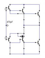
Remove both 68pF from C-B junction of VAS, also remove 27pF from collector node to opamp input and then connect 2 X 470pF from each base of predriver stage to ground and insert another 22ohm in the collector path of lower side 2N3773 driver and connect the CFB 1N4007 diode through it.
The Class-H mechanism in your schematic is direct copy of QSC......its not very reliable though.......The LM311 is very sensitive to local noise of switching itself. Sometimes during hard switching it usually false trigger many times, i have seen this in many amps.
The Class-H mechanism in your schematic is direct copy of QSC......its not very reliable though.......The LM311 is very sensitive to local noise of switching itself. Sometimes during hard switching it usually false trigger many times, i have seen this in many amps.
Attachments
Bouncing in commercial class H amplifiers? Really?
Good old audio analog designers going partially switchmode and showing their lack of skills?") )
)
I think that some hysteresis would be a good idea. Controlled dV/dt switching is also a good idea (then phase lead in the reference signal is required).
I also recommend powering everything except the output stage from independently filtered high voltage rails because switching produces (disturbing) ripple in the power rails (It should be locally filtered with CLC pi filters anyway...)
Good old audio analog designers going partially switchmode and showing their lack of skills?
)I think that some hysteresis would be a good idea. Controlled dV/dt switching is also a good idea (then phase lead in the reference signal is required).
I also recommend powering everything except the output stage from independently filtered high voltage rails because switching produces (disturbing) ripple in the power rails (It should be locally filtered with CLC pi filters anyway...)
Eva said:Bouncing in commercial class H amplifiers? Really?
Good old audio analog designers going partially switchmode and showing their lack of skills?
I think that some hysteresis would be a good idea. Controlled dV/dt switching is also a good idea (then phase lead in the reference signal is required).
I also recommend powering everything except the output stage from independently filtered high voltage rails because switching produces (disturbing) ripple in the power rails (It should be locally filtered with CLC pi filters anyway...)
Evita If you look at switching waveforms of QSC RMX series, they exhibit severe bouncing and sometimes false triggering of rails....
Meanwhile in my version of Class-H this type of behaviour is non-existant.......
its free from bouncing and false triggering...If you choose to filter the rails individually such as individual caps for low and high rails, then they exhibit a sort of pumping which i had seen in Phonic XP3000, but if you choose series stack capacitors, the power rails donot show pumping effect to that extent.
Try to clip a QSC PL325 and you will see that the adjacent rails were also falsely triggered..........
Eva said:I think that some hysteresis would be a good idea. Controlled dV/dt switching is also a good idea (then phase lead in the reference signal is required).
In PL6.0 we have implemented Hysteresis mode in order to over come false triggerring and the slope is based on predictive switching
Workhorse said:Remove both 68pF from C-B junction of VAS, also remove 27pF from collector node to opamp input and then connect 2 X 470pF from each base of predriver stage to ground and insert another 22ohm in the collector path of lower side 2N3773 driver and connect the CFB 1N4007 diode through it.
The Class-H mechanism in your schematic is direct copy of QSC......its not very reliable though.......The LM311 is very sensitive to local noise of switching itself. Sometimes during hard switching it usually false trigger many times, i have seen this in many amps.
IOW, compensate like a BGW500
. I guess pure lag comp works better with this type of o/p stage? I originally left the 27pF in place when I was experimenting, and no dice. I'll try building up another channel this week and hook up the CFP as you suggest - I hadn't tried that in combination with .001's to gnd off the VAS yet. The last QC I did had only 2 o/p's in parallel and the only thing that bothered it was insufficient supply bypassing. Which is why I was suspecting too much impedance through the commutators somehow mucking with things. More outputs in parallel would only make the parasitics worse. Does lag compensation make the o/p stage less susceptible to nonzero supply side impedance? The commutators seem to be reasonably well behaved in the board that I've stuck PNPs in. But I haven't hit it with 20k sines or square waves yet - switching seems to be ok with music or pure bass. But I am planning to take things a bit further - like trying to bridge into 2 ohms and see where it craps out. And to see if the larger IRFP2907's can be made to switch fast enough - for subwoofer duty at least. There's a 3-tier in the PCB layout phase. Would the QSC switch have better noise immunity if it were powered off a completely independent 15V supply? I was considering this for 'the big one' for a number of reasons.
Eva said:Good old audio analog designers going partially switchmode and showing their lack of skills?
I think that some hysteresis would be a good idea. Controlled dV/dt switching is also a good idea (then phase lead in the reference signal is required).
I also recommend powering everything except the output stage from independently filtered high voltage rails because switching produces (disturbing) ripple in the power rails (It should be locally filtered with CLC pi filters anyway...)
Workhorse said:
Evita If you look at switching waveforms of QSC RMX series, they exhibit severe bouncing and sometimes false triggering of rails....
Meanwhile in my version of Class-H this type of behaviour is non-existant.......
If you choose to filter the rails individually such as individual caps for low and high rails, then they exhibit a sort of pumping which i had seen in Phonic XP3000, but if you choose series stack capacitors, the power rails donot show pumping effect to that extent.
Try to clip a QSC PL325 and you will see that the adjacent rails were also falsely triggered..........
Come on people… if you take a closer look to the switching circuit, you will see some hysteresis done by the 470K resistor between output and + input of LM311; also the 47pF capacitor between bases of gate drivers and mosfet drain controls the switching dV/dt in collaboration with resistor and diode from output comparator. Also the positive driver could supply the gate with a voltage superior to the voltage rail. All this functions done with great simplicity and without special floating supplies.
This gate driver circuit is sensitive to external noise as any other circuit. Good layout is mandatory here or in any other circuit. If the main supply is not enough for the job, as it seems usual nowadays, don’t blame the switching circuit; class-H is a heavy compromise anyway.
False triggering could happen with any circuit but with this class-H arrangement could be catastrophic if happen with both switches simultaneously.
Mutual exclusive switching arrangement is prudent here…
Still unstable...
Connected the CFP in this manner, and then tried the lag comp (again). Without the 27pF cap, it's globally unstable, but this mode is nondestructive. With or without, with either the 68 pF Miller caps or 500pF on each side the gnd, the local loop on the negative side is still unstable above about -10V peak unless the rail is connected *directly* to the power suppy. Shorting emitter to base on the driver and rebiasing *will* fix it, but I'd wonder about how well it would drive 1 ohm loads that way. With the whole OPS switched to true complementary, it will work with the triple. So I'll build up some new boards that way so I can get on with what I intended to use this thing for.
Thanks for the help anyway, I had nothing to lose by trying a few more things.
Workhorse said:Remove both 68pF from C-B junction of VAS, also remove 27pF from collector node to opamp input and then connect 2 X 470pF from each base of predriver stage to ground and insert another 22ohm in the collector path of lower side 2N3773 driver and connect the CFB 1N4007 diode through it.
Connected the CFP in this manner, and then tried the lag comp (again). Without the 27pF cap, it's globally unstable, but this mode is nondestructive. With or without, with either the 68 pF Miller caps or 500pF on each side the gnd, the local loop on the negative side is still unstable above about -10V peak unless the rail is connected *directly* to the power suppy. Shorting emitter to base on the driver and rebiasing *will* fix it, but I'd wonder about how well it would drive 1 ohm loads that way. With the whole OPS switched to true complementary, it will work with the triple. So I'll build up some new boards that way so I can get on with what I intended to use this thing for.
Thanks for the help anyway, I had nothing to lose by trying a few more things.
TOINO said:Hi wg_ski
Maybe your problem is related with threshold voltage values in the comparators.
Do you have tried higher zenner values on the problematic half?
I doubt that's it because it seems to be independent of switching action. That negative side broke into oscillation even if the high rails were disconnected. I also ran it with the negative side locked to the high rail and it's not stable that way either. The high side switch would still work through all this, even though the current limit (light bulb) was dragging down the supply. If I totally bypassed everything on the - side (not running through the commutation diode or saturated HEXFET), it would be stable enough to operate. Just having the switch *there* seems to be making that CF arrangement just too touchy. I had hoped it was something simple I overlooked and that simple changes would fix it. PNPs in the negative side don't seem to care, even with the board being a rat's nest to do it. No hint of instability and commutation noise isn't objectionable with sine waves (totally masked with music, as usual).
The thresholds are one of the things I need to look at - they may need adjustment when I start pushing up the load current. The drops in the emitter resistors and base stoppers are going to add up. With an 8 ohm load in initial tests, there's no issue I can see yet. I was hoping to push peak load currents of 80+ amps to check that it doesn't drop out of saturation and see if the rise and fall times are workable. But first, I must have a stable amp I can beat on a little bit. The tranny powering this is a 4x30V 20A Signal beast. When I'm done with all the experimenting, I'll run 4 channels off that tranny and maybe be able to bridge into 2 ohms.
- Status
- This old topic is closed. If you want to reopen this topic, contact a moderator using the "Report Post" button.
- Home
- Amplifiers
- Solid State
- Class H amp - stability issies