A few days ago there was discussions about opamps in audio. Coincidentally, I was in the middle of exploring how good an opamp based power amp can be. I tried various scheme. I found one interesting scheme. It sounds good (for my ears with SMOMA songs  ) and have some interesting properties.
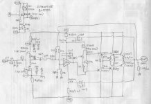
It is not originally my idea, it is based on schematic found on LM12 datasheet.
It starts with a buffer. I use K170BL+J74BL in self-biasing mode with 2x22ohm degeneration. In front, I put 10k+47pf to limit frequency response. Some member give advise not to use this 10k in Rg position (maybe smaller Rg like 100ohm), it's interesting to swap this Rg and found out how is the difference for sound reproduction. 10k+47pf making LPF.
This buffer gives harmonic cancelation, can be seen on the residual shape after nulled by distortion meter. For those who wants to try how 2nd harmonic sounds, between (A) and (B) can be replaced with alternative buffer above the main CCT.
The main amplifier is an inverting amplifier. The bridge balance (10k-2k2-10k33-2k2) + attenuation before the buffer (47k/(10k+47k)) makes total signal magnification about -30X.
The smaller the (10k33) value, the gain becomes bigger. If this 10k33 is decreased until 10k (the same with other bridge leg), the gain becomes infinite.
One interesting property is that the resistor between output and opamp's input are smaller (2k2) than resistor from opamp's input to external points (10k and 10k33). This makes the opamp takes care for the output node better than other opamp based power amp schemes (where usually the resistor from output node is bigger value than the resistors for inputs).
Another interesting property is that the supply for the opamp is bootstrapped +/-15V towards output node (thus towards the opamp's output node). Walt Jung in one of his papers wrote about distortion caused by voltage variation between opamp's output node and (-) supply terminal/die base. I think this is reduced very much with this scheme.
Beware of the 5pf (from +input to gnd) and zobel (100nf+2.7ohm) MUST be there to prevent oscilation. I tried many opamps TL081, NE5534, OP37, OPA637, OPA604, OPA134, LM318, and I "think" OP27 sounds better (for my ear). We can try how those opamps sounds, but beware, with some opamps, we need to put (CX=5pf) to prevent oscilation. With OP27, this CX is not used. One interesting property, this amp becomes more stable with 2uF cap//with speaker, I found this strange but interesting It is also interesting that with huge internal gain, the whole arrangement can be stabilized only with one small cap (5pF).
RX is there for experiment about opamp's bandwith. Mr. John Curl and Mr. Bob Cordell discussed this a few days ago. We can try and put RX (I try 1M and 470k), and I "think" putting RX=1M sounds better than bare (without RX) or with too small RX (470k).
Another intersting property, this scheme don't like base stoppers. I put base stoppers and it becomes worse. Without base stopper anywhere it performs the best. Another strange but interesting property
Between emitor-emitor of the predriver and driver (bridging 680ohm and 150ohm) is there to keep all drivers on. I choose 680ohm and 150ohm based on heat dissipation. The bias is about 15mV accross 0.15ohm RE. The residual is simple, not complex, one good clue
The VBEmultiplier transistor (BC546) must be put on heatsink for thermal compensation.
) and have some interesting properties. It is not originally my idea, it is based on schematic found on LM12 datasheet.
It starts with a buffer. I use K170BL+J74BL in self-biasing mode with 2x22ohm degeneration. In front, I put 10k+47pf to limit frequency response. Some member give advise not to use this 10k in Rg position (maybe smaller Rg like 100ohm), it's interesting to swap this Rg and found out how is the difference for sound reproduction. 10k+47pf making LPF.
This buffer gives harmonic cancelation, can be seen on the residual shape after nulled by distortion meter. For those who wants to try how 2nd harmonic sounds, between (A) and (B) can be replaced with alternative buffer above the main CCT.
The main amplifier is an inverting amplifier. The bridge balance (10k-2k2-10k33-2k2) + attenuation before the buffer (47k/(10k+47k)) makes total signal magnification about -30X.
The smaller the (10k33) value, the gain becomes bigger. If this 10k33 is decreased until 10k (the same with other bridge leg), the gain becomes infinite.
One interesting property is that the resistor between output and opamp's input are smaller (2k2) than resistor from opamp's input to external points (10k and 10k33). This makes the opamp takes care for the output node better than other opamp based power amp schemes (where usually the resistor from output node is bigger value than the resistors for inputs).
Another interesting property is that the supply for the opamp is bootstrapped +/-15V towards output node (thus towards the opamp's output node). Walt Jung in one of his papers wrote about distortion caused by voltage variation between opamp's output node and (-) supply terminal/die base. I think this is reduced very much with this scheme.
Beware of the 5pf (from +input to gnd) and zobel (100nf+2.7ohm) MUST be there to prevent oscilation. I tried many opamps TL081, NE5534, OP37, OPA637, OPA604, OPA134, LM318, and I "think" OP27 sounds better (for my ear
). We can try how those opamps sounds, but beware, with some opamps, we need to put (CX=5pf) to prevent oscilation. With OP27, this CX is not used. One interesting property, this amp becomes more stable with 2uF cap//with speaker, I found this strange but interesting It is also interesting that with huge internal gain, the whole arrangement can be stabilized only with one small cap (5pF). RX is there for experiment about opamp's bandwith. Mr. John Curl and Mr. Bob Cordell discussed this a few days ago. We can try and put RX (I try 1M and 470k), and I "think" putting RX=1M sounds better than bare (without RX) or with too small RX (470k).
Another intersting property, this scheme don't like base stoppers. I put base stoppers and it becomes worse. Without base stopper anywhere it performs the best. Another strange but interesting property
Between emitor-emitor of the predriver and driver (bridging 680ohm and 150ohm) is there to keep all drivers on. I choose 680ohm and 150ohm based on heat dissipation. The bias is about 15mV accross 0.15ohm RE. The residual is simple, not complex, one good clue
The VBEmultiplier transistor (BC546) must be put on heatsink for thermal compensation.
Attachments
1) I'd take my feedback signal to the op-amp from the output of the power stage, i.e. midpoint of the emitter ballast resistors that connects to the load, not from the output of the op-amp. This corrects any non-linearity in the emitter-follower chain also by dividing it by the loop-gain.
2) I'd drop the input FET buffer (which is running as an open-loop source follower) and make the op-amp non-inverting to provide high input impedance. That also removes a bunch of caps and resistors from the signal path, linearizing things a bit.
3) I'd consider simplifying things by using a single-stage darlington power output pair instead of the pre-driver/driver/power stage.
Tube_Dude said:Hi
The 2k2 feedback resistor that come from the output and connect to the non- inverting input of the OP-AMP, is providing positive feedback.
Certainly as it is, it will oscillate
Jorge
I do not agree, two 2k2 and 10k resistors provide some common signal to both inverting and non-inverting inputs of an op-amp.
The op-amp has floating supplies, so inputs signals must stay within their voltages.
Feedback (negative!!) is provided by 330R in series with 10k and 22u at inverting input.
darkfenriz said:
Jorge
Feedback (negative!!) is provided by 330R in series with 10k and 22u at inverting input.
Hi darkfenriz , long time no see...
In that case the gain will be 2k2/(10k+0,33 ) = 0,2 times
Less than 1
Hi, Linuxguru,
1. The feedback is indeed from output node via 2k2.
2. Yes, you could do that
3. I use triple darlington, because the VBE multiplier is only biased about 3mA (from K30 IDSS).
Hi, Tubedude,
At first I'm confused too about how to calculate gain of this scheme. It is different than non-inverting or inverting voltage divider calculation. It is based on bridge balance calculation. Feedback is coming to both inverting and non-inverting input of the opamp via 2x2k2. The gain of the amp (plus the attenuation of 10k+47k in input) is about -30X.
It can be seen here :
http://www.diyaudio.com/forums/showthread.php?s=&threadid=105976&highlight=
lumanauw said:
Hi, Tubedude,
At first I'm confused too about how to calculate gain of this scheme. It is different than non-inverting or inverting voltage divider calculation. It is based on bridge balance calculation. Feedback is coming to both inverting and non-inverting input of the opamp via 2x2k2. The gain of the amp (plus the attenuation of 10k+47k in input) is about -30X.
It can be seen here :
http://www.diyaudio.com/forums/showthread.php?s=&threadid=105976&highlight=
Hi Lumanauw
In the aplication note in the link you gave, the output stage has voltage gain and no current gain.
All the current is given by the LM12.
In your schematic your output stage as no voltage gain , only current gain.
Is a very strange circuit I need some more time to figure it out...
Indeed it seems strangeIn your schematic your output stage as no voltage gain , only current gain.
the opamp's +rail, -rail and output pin are static towards amp's output node. The whole opamp is swinging following the amp's output voltage (the supply is bootstrapped via 100uF capacitor). Even it seems the opamp has no voltage gain, the whole thing has gain about -30 (inverting). The explenation by Sawreyrw is how to calculate the gain.
But above all the strangeness, it sounds good
lumanauw said:
Indeed it seems strange
So , let me see.
If we have 40 volts at the output, as the input is bootstrapped , we have the inverting and the non inverting input swinging also 40 volts above ground.
How we drive this, with how many volts?

Hi, Tube_Dude,
Your question is very good indeed. I asked the very same question. After some time, the explenation is quite simple.
In my schematic drawing, to the (-) input of the OP27 there are 2 resistors, 10k and 330ohm.
To make imagination easier, swap the place of 330 and 10k, after 22uF cap there is 330ohm first and then 10k attached to (-) input.
This is an inverting amp. If the output is sitting at +40V, then what is the input voltage at the left side of the 330ohm (=right side of 22uf).
The bridge is not balanced. One leg has 10k, the other leg has 10k+330ohm.
If the lower end of the 10k (attached to the (+) input) is sitting at GND (=0V), then the left end of the other 10k (attached to (-) input) must be at the same voltage (=0V virtual gnd).
The total resistor between output (+40V) and 0 (GND) are 10k+2k2=12k2.
Then, because the junction of 10k and 330ohm is sitting at (0V virtual gnd), it makes the other end of 330ohm attached to 22uF is sitting at = -(330/12k2)x40V = -1V08.
To drive the output to +40V, we need input of -1V08 at the right side of 22uF.
Hi, Toquito5000,
Are you Mas Atok yang suka di Ciptaswaratama?
Good question. Since the +/-15 is for the opamp is bootstrapped towards output, clipping is likely to happen. Clipping prevention (soft) can be done by putting diodes from base 2N5551 and 2N5401 to rails, or by string of diode (or led) back to back between pin1 and pin8 of OP27 (hard). You can try and decide which sound you like.
- Status
- This old topic is closed. If you want to reopen this topic, contact a moderator using the "Report Post" button.
- Home
- Amplifiers
- Solid State
- Opamp based power amp