Well, here's the beast I put together for a test bed, both bench and listening:

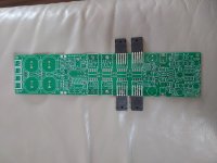
It uses the single Brian Bell-designed Leach amplifier board, laid out for use with plastic-cased output transistors--simplified wiring very neatly compared to TO-3 socket devices. Similar in appearance to a Hafler SE-series small amplifier that I've long admired and the first amplifier I've built that doesn't look industrial-ugly.

A closeup of the NJL1302/3281 Thermal Trak and MJL1302/3281 transistors with current monitor clip leads. Note charge suckout capacitor between the driver emitters for improved high frequency distortion. This may be working better with these high speed transistors than did the MJL21193/4 transistors I installed initially. A 10uF capacitor worked a bit better and seems to reduce high-order distortion products on the oscilloscope display, a result I was hoping for with these devices.
Depending on bias settings, my Fluke digital thermometer reads heat sink temps up to 150F, a lot hotter than I'd prefer to run for other than test purposes.

My Tektronix AA-501A based distortion test set, showing a 1 kHz signal at about 3 watts.
It uses the single Brian Bell-designed Leach amplifier board, laid out for use with plastic-cased output transistors--simplified wiring very neatly compared to TO-3 socket devices. Similar in appearance to a Hafler SE-series small amplifier that I've long admired and the first amplifier I've built that doesn't look industrial-ugly.
A closeup of the NJL1302/3281 Thermal Trak and MJL1302/3281 transistors with current monitor clip leads. Note charge suckout capacitor between the driver emitters for improved high frequency distortion. This may be working better with these high speed transistors than did the MJL21193/4 transistors I installed initially. A 10uF capacitor worked a bit better and seems to reduce high-order distortion products on the oscilloscope display, a result I was hoping for with these devices.
Depending on bias settings, my Fluke digital thermometer reads heat sink temps up to 150F, a lot hotter than I'd prefer to run for other than test purposes.
My Tektronix AA-501A based distortion test set, showing a 1 kHz signal at about 3 watts.
Are the ThermalTrak's a single die? Servicing power amps with Japanese O/P transistors with integral diodes (I forgot but I think they were Sankens.
I've seen an output transistor short (collector) to the thermal trak diode, which energizes and destroys more in the diode string. So you can end up with good output transistors but damaged diodes I would run a small fusible resistor or something to limit string current if a fault occurs.
Upcoming July 2011 Silicon Chip Magazine has the Ultra-LD Mk III amplifier and it "addresses the shortcomings of the internal tracking diodes in the ThermalTrak power transistors". Should be an interesting read. They'd used ThermalTrak's in their Ultra-LD Mk II amplifier design and had problems with bias tracking.
I've seen an output transistor short (collector) to the thermal trak diode, which energizes and destroys more in the diode string. So you can end up with good output transistors but damaged diodes
I would run a small fusible resistor or something to limit string current if a fault occurs.Upcoming July 2011 Silicon Chip Magazine has the Ultra-LD Mk III amplifier and it "addresses the shortcomings of the internal tracking diodes in the ThermalTrak power transistors". Should be an interesting read. They'd used ThermalTrak's in their Ultra-LD Mk II amplifier design and had problems with bias tracking.
Excellent idea guys - I was about to start a new thread but luckily found this post first. Has anyone actually done any testing on this since?
The two potential problems I see are:
1) The faster, higher gain transistors may cause problems with parasitic oscillation, and
2) The Thermaltrak internal diodes don't have the same temperature characteristics as 1N4004 and may not compensate correctly as used in this design.
It would be nice to know if anyone has actually tested for either of these potential pitfalls. If not, I'll try it myself and post the results, but probably not for a little while.
Hi,
I was an FAE for ON and tried out the ThermalTraks in a Harman Kardon Signature 1.3 module. The diode is an ultrafast rectifier die stuck on the same flag as the transistor die, so the thermal coupling is amazing. The original Sig 1.3 amplifiers idled at 100w and had about 0.002% distortion. When I flipped on the modified module, I measured no bias and thought 'Pfft, that diode bias doesn't work', but the distortion analyzer clicked a bit and settled on 0.005% distortion. The module was idling at about 1 watt bias and rock solid. On an amp with good thermal compensation, the bias wanders around a bit (blow on the heat sinks), but in the ThermalTrak the bias on the meter just sits there and stares at you.
The Sig 1.3 has 3 outputs in parallel in a triple darlington, so you get the right number of diodes. I think the emitter resistors might have been 0.33 ohms and I added a few tens of ohms in the diode string. The diodes aren't, strictly speaking, compensating the darlington driver transistors, but the currents are all proportional, so it all tracks.
The original Sig 1.3 has all fancy Japanese transistors, but the module I modified was a prototype that was all blown up, so I just got it going with junk MPSA06/MPSA56 transistors, so you may be able to do much better than the 0.005%. I actually never even bothered to improve it after it came up on the first try. You also won't need the bias adjust pot once you get it going with fixed resistors. That's supposed to be the big deal with ThermalTrak.
Cheers
Hi mlise,
Thanks for sharing your experience. From what I've read, contrary to the Thermaltrak datasheet application notes most OPS configurations really still require some sort of Vbe multiplier arrangement in addition to the Thermaltrak diodes to achieve good quiescent stability - for example Silicon Chip magazine has recently published an updated amplifier design (ULD mkIII) where they have used a Vbe multiplier with the diodes to improve thermal stability since in the original design (mkII) they had relied on the diodes only and many constructors experienced thermal problems. And that design is a simple EF OPS, not a triple. Self and Cordell both go into this in detail in their excellent books also.
My interest is mainly in whether they work well in Leach amp - it already has the combined Vbe multiplier + diodes arrangement so seems like the perfect candidate. However, as mentioned I worry that the faster, higher gain devices will be more prone to parasitics in the triple OPS, and also I gather the forward voltage of the Thermaltrak diodes is lower than the 1N4004s used in the Leach, so perhaps the Vbe mulitiplier coeffiecient will need to be adjusted to compensate. The whole thermal compensation issue seems to be extremely complex if done properly, so being lazy I figured it'd be easier to just try it and see, or better still see if someone else has...
I feel that my Leach amp takes about 15 mins after switch-on from cold to start sounding really good, and my guess is that this is due to higher crossover distortion while the bias is slowly coming up to a stable point as the heatsinks warm up. I'm hoping that improved thermal traking by using the diodes in the Thermaltraks will improve things in this regard.
Cheers
Back to working on my Leach amplifier prototype with ThermalTrak transistors. Of course, there are issues.
Rumors that ONSemi is canceling the ThermalTrak line notwithstanding, I have only two sets of the devices to make a stereo amplifier. So, using another set of 'regular' MJL outputs, I epoxied 1N4004 diodes to the cases above the silicon dies to make a hybrid set for both channels to get things rolling.
On testing the first channel, I immediately found a considerable rise in distortion and bias current with frequency, especially starting at 10kHz. At 20 kHz, the crossover distortion notch is plainly visible unless I considerably increase bias and that leads to a very hot heatsink. 20kHz distortion is almost two orders of magnitude higher than 1 kHz at full power and a couple of times I popped a 5 amp rail fuse (no damage to the amplifier) with audible stress from the power transformer. Rail voltages fall to 50 volts or a little lower.
Obviously, something's not right. I'm going to experiment with base stopper resistors and base to collector snubbers to see if there's oscillation at some extremely high frequency that's not showing on the 'scope.
Distortion at lower frequencies and modest power levels is .007% or thereabouts, though I feel the noise floor is a little high. The circuit board is a unique design by BrianGT, who doesn't seem to be active lately; the other channel will have to be kludged from my main Leach amplifier's 4.5 board with (short) jumpers.
If my new job at Carlisle Interconnects works out, I plan to acquire a bunch of ThermalTrak devices to continue experiments with a full complement of devices and plenty of spares. I'm eager to listen to a working amplifier with these transistors, hopefully taking full advantage of their close thermal tracking and improved linearity and Ft.
Good to see someone's still working on this.
Are you sure your measurements are abnormal? Leach's THD curve for the amp shows about 0.2% at 10kHz. When I measured mine (built with MJL21193/4 devices) it matched this fairly well - 1kHz THD was about 0.006% but rose to about 0.15% at 10kHz.
I used a thick (5mm) bar of aluminium the width of the board that covers the transistor faces and clamps them evenly to the heatsink. An added bonus of this method is that it allowed me to mount the diodes in the bar, which tracks the device temperatures better and quicker due to its lower thermal mass. Not quite as good as having the diodes in the packages though...
If you read the FAQ section, Leach is careful to point out that the output device fT is not a limiting factor on bandwidth in his design, so don't expect the performance to change much if any. Maybe you are getting parasitic oscillation due to the higher speed devices. The last revision of the design has 10R base stoppers - have you used these?
the Leach has two NFB routes.
The Low frequency one is global and includes the output stage.
There is a High frequency NFB that excludes the output stage.
This inherent feature will give a higher high frequency distortion simply because there is little to no feedback around the output stage at higher frequencies.
This leads to an amplifier that is easier to stabilise, but the compromise, in my view, will be higher distortion.
Bias is thermally stable, but goes up dramatically with frequency; it's definitely different from my other amplifiers. The increase in bias current seems nonlinear, and the reappearance of the crossover notch is very undesirable.
I might try lifting that internal feedback loop to see what happens. I'm not 100% certain that the layout on BrianGT's board is perfect or that I might have gotten a part wrong in building it.
In my initial testing a while back, I used MJL21193/94 devices and I don't recall having problems. The bias diodes were glued to the heatsink, putting them on that metal bar seems like a better idea. As a further experiment, I removed the base stoppers and installed a speedup capacitor on the driver stage, but observed very little difference in distortion for 2 uF, and not much more with 10 uF. I'm going to reinstall the stoppers and take out that capacitor, and see what happens.
Might have already done some of this last weekend, but the current Seattle heat wave has made it too bloody hot in my workroom during the afternoon and evenings.
I haven't tried running IM tests with my Tektronix AA501A analyzer; this test set can run both SMPTE and CCIF tests, but I need to dig into the docs to be sure I'm seeting it up correctly. THD testing is very easy to do, and I monitor the distortion products on an oscilloscope.
Last edited:
Damon:
I haven't read all the way through the thread yet, but sometimes the symptoms you describe point to common mode conduction - both N and P outputs coming on hard at the same time.
mlloyd1
I haven't read all the way through the thread yet, but sometimes the symptoms you describe point to common mode conduction - both N and P outputs coming on hard at the same time.
mlloyd1
Back to working on my Leach amplifier prototype with ThermalTrak transistors. Of course, there are issues.
Rumors that ONSemi is canceling the ThermalTrak line notwithstanding, I have only two sets of the devices to make a stereo amplifier. So, using another set of 'regular' MJL outputs, I epoxied 1N4004 diodes to the cases above the silicon dies to make a hybrid set for both channels to get things rolling.
On testing the first channel, I immediately found a considerable rise in distortion and bias current with frequency, especially starting at 10kHz. At 20 kHz, the crossover distortion notch is plainly visible unless I considerably increase bias and that leads to a very hot heatsink. 20kHz distortion is almost two orders of magnitude higher than 1 kHz at full power and a couple of times I popped a 5 amp rail fuse (no damage to the amplifier) with audible stress from the power transformer. Rail voltages fall to 50 volts or a little lower.
Obviously, something's not right. I'm going to experiment with base stopper resistors and base to collector snubbers to see if there's oscillation at some extremely high frequency that's not showing on the 'scope.
Distortion at lower frequencies and modest power levels is .007% or thereabouts, though I feel the noise floor is a little high. The circuit board is a unique design by BrianGT, who doesn't seem to be active lately; the other channel will have to be kludged from my main Leach amplifier's 4.5 board with (short) jumpers.
If my new job at Carlisle Interconnects works out, I plan to acquire a bunch of ThermalTrak devices to continue experiments with a full complement of devices and plenty of spares. I'm eager to listen to a working amplifier with these transistors, hopefully taking full advantage of their close thermal tracking and improved linearity and Ft.
Bias is thermally stable, but goes up dramatically with frequency; it's definitely different from my other amplifiers. The increase in bias current seems nonlinear, and the reappearance of the crossover notch is very undesirable.
I might try lifting that internal feedback loop to see what happens. I'm not 100% certain that the layout on BrianGT's board is perfect or that I might have gotten a part wrong in building it.
In my initial testing a while back, I used MJL21193/94 devices and I don't recall having problems. The bias diodes were glued to the heatsink, putting them on that metal bar seems like a better idea. As a further experiment, I removed the base stoppers and installed a speedup capacitor on the driver stage, but observed very little difference in distortion for 2 uF, and not much more with 10 uF. I'm going to reinstall the stoppers and take out that capacitor, and see what happens.
Might have already done some of this last weekend, but the current Seattle heat wave has made it too bloody hot in my workroom during the afternoon and evenings.
I haven't tried running IM tests with my Tektronix AA501A analyzer; this test set can run both SMPTE and CCIF tests, but I need to dig into the docs to be sure I'm seeting it up correctly. THD testing is very easy to do, and I monitor the distortion products on an oscilloscope.
What do you mean by increasing bias at HF? Are you trying to measure it with a signal input? Then you would be measuring the signal as well....
I like the sound of the Leach amp despite its higher-than-average distortion at HF. In my view it is a fine example of a well engineered amp that shows how poorly a simplistic THD curve corresponds with audible distortion and sound quality. Trying to improve its THD by modifying it with speedup caps etc is all very well but how do you know it will improve the sound quality and not make it worse? Especially if the stability is compromised. If you want an amp with very low THD there are plenty of designs out there that perform much better in this regard (but probably sound worse
)I don't think there should be visible crossover distortion at 20 kHz when the bias is set to a nominal level and there's no crossover distortion at 1 kHz. This particular amplifier is not very happy at higher frequencies; other Leach amplifiers I have built don't behave like this.
Long weekend so I hope to have time to delve deeper into this problem.
Long weekend so I hope to have time to delve deeper into this problem.
After much difficulty and procrastination, I finally have a stereo chassis using two not-quite-identical Leach amplifier boards running with high Ft Thermaltrak transistors. There are a couple of issues with the measured performance; one channel appears to exhibit cross-conduction above 10 kHz and high power, and somewhat 'dirty' distortion residuals; the other channel, much less so.
It's taken over five years for me to get to this point: actually listening to the thing.
The real point of the exercise of course, is to take advantage of the high Ft and linearity of the perforated emitter transistors and the close thermal tracking of the internal bias diodes. I'm open to thoughts on how to modify the Leach design to exploit that higher speed; simply changing the Miller capacitors on the VAS stage is not without perils.
And so far the amplifier sounds pretty good on complex program material.
I wasn't expecting an audible difference just because of the perforated emitter transistors and the improved thermal tracking, but it may be so. I'm not complaining.
I turned the bias down enough to suppress crossover distortion rather than go for near-Class A to minimize distortion; runs only lukewarm now without audible distortion. Contemplating changing the VAS transistors to cascodes as Leach did on the Superamp.
Last edited:
It's taken over five years for me to get to this point: actually listening to the thing.
Now that is perseverance
Have you been doing Ltspice simulations of your design?
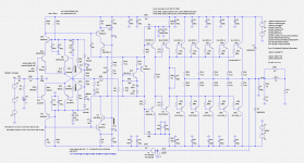
I've barely begun to learn how to use Ltspice. If I actually want to change the VAS to a cascode, I probably ought to do with in simulation first. There is a Spice model on Leach's web site.
I have a Tektronix AA501A distortion analyzer; the distortion is reasonably low, but not quite as clean of higher-order distortion products as I could wish.
I have a Tektronix AA501A distortion analyzer; the distortion is reasonably low, but not quite as clean of higher-order distortion products as I could wish.
........ If I actually want to change the VAS to a cascode, I probably ought to do with in simulation first. There is a Spice model on Leach's web site.
This is my ThermalTrak-ed Leach with Hawksford Cascode VAS. I ditched the cross-over feedback loops and replaced them with simple global feedback. Simulation shows adequate stability margins, and a better than 0.002% distortion at 20KHz full power. and I have never detected instability with the actual build. This is my daily amp driving a pair of 4-ohm PSB Stratus Gold-i floor standers in the living room. The build was done on a gutted Citation 16 chassis. I have a thread "pimped Citation" for that, but it was plain Leach Low TIM plus ThermalTrak at that moment. VAS and feedback mod was done later when I learned a bit in using LTspice.
It did take me some effort in getting the bias control stability right. I ended up pulling it off by using Bob Cordell's Figure 14.19(a) combined with a constant current control.
Attachments
If you are new to Ltspice, I do suggest that you buy/read Bob Cordell's Power Amp book. Also I just discovered yesterday that user "mooly" has started a Ltspice thread, so that should help you get up to speed as well.
http://www.diyaudio.com/forums/software-tools/260627-installing-using-ltspice-beginner-advanced.html
Thx "nattawa" for your contribution, more stuff for me to learn as well.
http://www.diyaudio.com/forums/software-tools/260627-installing-using-ltspice-beginner-advanced.html
Thx "nattawa" for your contribution, more stuff for me to learn as well.
I will try them as wellHi mlise,
Thanks for sharing your experience. From what I've read, contrary to the Thermaltrak datasheet application notes most OPS configurations really still require some sort of Vbe multiplier arrangement in addition to the Thermaltrak diodes to achieve good quiescent stability - for example Silicon Chip magazine has recently published an updated amplifier design (ULD mkIII) where they have used a Vbe multiplier with the diodes to improve thermal stability since in the original design (mkII) they had relied on the diodes only and many constructors experienced thermal problems. And that design is a simple EF OPS, not a triple. Self and Cordell both go into this in detail in their excellent books also.
My interest is mainly in whether they work well in Leach amp - it already has the combined Vbe multiplier + diodes arrangement so seems like the perfect candidate. However, as mentioned I worry that the faster, higher gain devices will be more prone to parasitics in the triple OPS, and also I gather the forward voltage of the Thermaltrak diodes is lower than the 1N4004s used in the Leach, so perhaps the Vbe mulitiplier coeffiecient will need to be adjusted to compensate. The whole thermal compensation issue seems to be extremely complex if done properly, so being lazy I figured it'd be easier to just try it and see, or better still see if someone else has...
I feel that my Leach amp takes about 15 mins after switch-on from cold to start sounding really good, and my guess is that this is due to higher crossover distortion while the bias is slowly coming up to a stable point as the heatsinks warm up. I'm hoping that improved thermal traking by using the diodes in the Thermaltraks will improve things in this regard.
Cheers
Attachments
- Home
- Amplifiers
- Solid State
- Leach To Thermal Trak