There is a school of thought that says bipolar transistors produce a better sound than fets because they are more linear. This might be so; I haven't experimented to find out. One thing I do know though is that bipolars are a lot more fragile than fets because of second breakdown effect which limits their wattage rating at higher voltages. So for a high power amplifier with rails of 60 to 80v or more you start to need very expensive transistors and lots of them in parallel!
I was looking at one of Nelson Pass' patents using a pair of cascoded mosfets and then an idea occurred to me - why not replace the inner pair of power devices with bipolars to get the advantage they apparently provide? In the cct attached, the bipolars are run at a virtually constant collector-emitter voltage of about 11-12v. This is really important because if you look at the safe operating area graph of a power bipolar you can see that it will take full rated current up to about 10 volts or so, then it is dissipation limited, then further on it is hobbled by second breakdown limits. However if we keep the CE voltage at a constant 12 volts or so then we can run the transistor at it *full* rated collector current without popping it! What's more, we now don't have to use a fearfully expensive high voltage high wattage transistor, all we need is one that has a suitable current rating and is fast enough for our purposes.
All the really hard work is done by the fets, and for this kind of thing there is nothing better. Also, it is not really necessary to use a P-channel for the bottom fet, you could use a second N-channel and a small P-channel to make a quasi complementary setup. Absolute finesse is not important here, what matters is brute strength, putting a roof over the heads of the comparatively delicate bipolars to shield them from the storm. Within that protected space they can excel at what they do best. The husband is swinging the sledgehammer and the wife is doing the embroidery.
Attachments
Perfectly workable, but operates on the premise that
BJT's are inherently more linear than Mosfets.
Either device can be set up in conditions that favor it
over the other. It happens that nature favors the
Mosfet at higher current, and that is why it makes such
a great Class A gain device in output stages.
You might be interested in my patent #5,343,166 "Efficient
high fidelity audio power amplifier" which describes using
cascode in an arrangement which allows the cascoded gain
transistor to be biased at higher currents than pass through
the output stage. In this manner you could easily run the
cascoded device in "super Class A" without incurring much
of an efficiency penalty.
which brings up a question...
Is it better for the cascode fet to swing its gate from the
output or input, and why? I've seen NP to do it in his Audio
magazine article from the output. In principle, the difference is
of course, only a Vbe drop, are there more subtle sonic effects?
I can see that connected as it is from the input side, there
will be additional loading to the preceeding gain stage and that
being a sensitive stage, it may be better to have it see a
well behaved load.
I realise Circlotron's idea is just related to output stages, I thought
I'd drop in a question since this is related.
Thanks for any explanation,
Yv
I had another look at some transistor characteristic curves and generally they are cramped together somewhat at the left side and diverge a bit at the right side. If you draw a load line from bottom right to top left (assuming a straight line resistive load for simplicity) you will get nonlinearity the further you go northwest into the more densely packed lines. The cct and suggestion I drew would make the loadline appear vertical to the transistors, a bit of an improvement. But thinking about it some more, if you had the Vce at say 2v at idle and increased the collector voltage faster than the emitter voltage went up so that as the emitter goes up the Vce of the working transistor actually *increases*, then the loadline would appear to slope to the right. The ideal setup (I think  ) would be to have the load line traverse a path where the horizontal lines of the curves are equally spaced all the way wherever the load line crosses them, even if the load line had to be made wiggly by juggling the instantaneous Vce.
) would be to have the load line traverse a path where the horizontal lines of the curves are equally spaced all the way wherever the load line crosses them, even if the load line had to be made wiggly by juggling the instantaneous Vce.
Circlotron
>So I've killed this thread too, huh?<
No way. Just browsed through it for the first time a few minutes ago. Nice, interesting topic.
A number of commercial power amps from the big Japanese companies (Pioneer, Yamaha, Denon, and probably more) operate in a roughly similar manner as the idea that you mention.
I would most likely drive the cascode devices from the input side, rather than the output. In the case of referencing from the output side, anything happening on the load will affect both the output device and the cascode which is nominally supposed to help protect it.
Rather than using MOSFET, an option would be to use some low-voltage MOSFETs which have comparatively lower capacities (pF) relative to the amount of current that they can handle.
Looking at Nelson's patent, it may be interesting to configure the current source as a floating circuit powered from a separate power supply. The floating source would provide most of the current needed, while the cascode sources would maintain a fixed and small voltage across the ouput devices.
You can see this line of thinking in the following circuit from the Kamijo Evolve website, although this is an SE rather than PP:
http://www.ne.jp/asahi/evo/amp/2sk1380/zu9.gif
The intro page for this project is at:
http://www.ne.jp/asahi/evo/amp/2sk1380/intro.htm
The main text is at:
http://www.ne.jp/asahi/evo/amp/2sk1380/report.htm
Be forewarned that most of the text is in Japanese.
regards, jonathan carr
Those of you who has trouble with japanese can test this translation service.
http://world.altavista.com/
http://world.altavista.com/
"So I've killed this thread too, huh?"
No, its just an old thread.
Quite a while back I brought up Jan Didden's 200W cascode amplifier. It was published in Audio Amateur many years ago and used 65Mhz 5A $1 plastic outputs cascoded with $2 metal devices with 150W SOA at 100V. I also pointed out how easy it Would be to add the Nelson Pass 'Efficient high fidelity audio power amplifier' circuit.
I think it would be a natural, especially for multi-channel home theater setups. Run it class A up to 15W or so, and then the amp cascodes itself for up to 100W. If you made an ordinary 100W class AB amplifier and biased into class A for the first 15W, and then stuffed 5 channels into a chassis: it would run as hot as your stove.
cascodes
This was also done by Sony in the late 70's as I found out when I bought a used TA-N7. It uses bipolar outputs cascoded with the then just-developed VFETs. I'll look at the schematics (courtesy www.schaltungsdienst.de) to see how exactly the cascodes are biased.
Jan Didden
This was also done by Sony in the late 70's as I found out when I bought a used TA-N7. It uses bipolar outputs cascoded with the then just-developed VFETs. I'll look at the schematics (courtesy www.schaltungsdienst.de) to see how exactly the cascodes are biased.
Jan Didden
Circlotron said:There is a school of thought that says bipolar transistors produce a better sound than fets because they are more linear. This might be so; I haven't experimented to find out. One thing I do know though is that bipolars are a lot more fragile than fets because of second breakdown effect which limits their wattage rating at higher voltages. So for a high power amplifier with rails of 60 to 80v or more you start to need very expensive transistors and lots of them in parallel!
I was looking at one of Nelson Pass' patents using a pair of cascoded mosfets and then an idea occurred to me - why not replace the inner pair of power devices with bipolars to get the advantage they apparently provide? In the cct attached, the bipolars are run at a virtually constant collector-emitter voltage of about 11-12v. This is really important because if you look at the safe operating area graph of a power bipolar you can see that it will take full rated current up to about 10 volts or so, then it is dissipation limited, then further on it is hobbled by second breakdown limits. However if we keep the CE voltage at a constant 12 volts or so then we can run the transistor at it *full* rated collector current without popping it! What's more, we now don't have to use a fearfully expensive high voltage high wattage transistor, all we need is one that has a suitable current rating and is fast enough for our purposes.
All the really hard work is done by the fets, and for this kind of thing there is nothing better. Also, it is not really necessary to use a P-channel for the bottom fet, you could use a second N-channel and a small P-channel to make a quasi complementary setup. Absolute finesse is not important here, what matters is brute strength, putting a roof over the heads of the comparatively delicate bipolars to shield them from the storm. Within that protected space they can excel at what they do best. The husband is swinging the sledgehammer and the wife is doing the embroidery.
Circlotron,
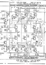
The circuit of the TA-N7 is very similar to yours, but Sony took advantage of the VFETs. The can be automatically biased for about 15-20 VDC gate-source voltage, because that is their pinch-off voltage I think it is called.
Look at this diagram: the cascode FETs have their gates directly connected to the output terminal, not needing the offset zeners. The collectors of the main bipolars are then automatically at 15-20V. Neat!
Jan Didden
Attachments
- Status
- This old topic is closed. If you want to reopen this topic, contact a moderator using the "Report Post" button.
- Home
- Amplifiers
- Solid State
- Cascode cct minimises SOAR requirements of output bipolars.