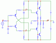
I have tried once...but i had problems with off set.
Please, instruct us how to control the off set and suggest some values to this schematic.
Was one schematic that our forum friend Ostry provided me and i could not control the off set...not exactly this one you suggest..but alike related the topology.
regards,
Carlos
Please, instruct us how to control the off set and suggest some values to this schematic.
Was one schematic that our forum friend Ostry provided me and i could not control the off set...not exactly this one you suggest..but alike related the topology.
regards,
Carlos
Hi Carlos,
yes, the DC offset depends on sameness of N and P halves. It is not that bad, though, even with change of
temperature. In case you disconnect the load, the DC increases substantially. Also, for higher ohm load the DC
increases. And gain increases with load, this is a current output amplifier.
The DC servo injecting current into input node would be the cure, as Ipanema has mentioned
Best,
Pavel
yes, the DC offset depends on sameness of N and P halves. It is not that bad, though, even with change of
temperature. In case you disconnect the load, the DC increases substantially. Also, for higher ohm load the DC
increases. And gain increases with load, this is a current output amplifier.
The DC servo injecting current into input node would be the cure, as Ipanema has mentioned

Best,
Pavel
Why is that?No, unless you want the amplifier to blow.
Leolabs said:Stability???
AC stability stability should be excellent, based on amp of almost same architecture, but voltage output, and on simulation plots of this current output version.
Without source resistors you leave output stage conrolled by transconductance of output transistors.
1. N and P chanel transistors don't have the same transconductance, so output current will not be symetric.
2. without source resistors your amplifier will blow itself when heated, unless you want to have fireworks it's not a good thing.
So, my point is, if you put there source resistors, you lower transconductance of transistors making them more similar and linear. Also change of bias current will be less noticable with them (I usually use 0R47 resistors in circuits like this)
Pavle:
I would be. I have been experimenting with current feedback (using your modified headphone amplifier), and the results are very encouraging. However, I need more power than the heasphone amplifier provides. Consequently, do you think that you could experiment with biasing/output transistors selection for about 5-8 W into 8 ohms? I do not need more, and do not want to build a heater. ;-)
Kindest regards,
M
P.S. Sorry I failed to visit you in Prague, I had some family issues.
M
. . ., I could try to build it, if someone was interested in results
I would be. I have been experimenting with current feedback (using your modified headphone amplifier), and the results are very encouraging. However, I need more power than the heasphone amplifier provides. Consequently, do you think that you could experiment with biasing/output transistors selection for about 5-8 W into 8 ohms? I do not need more, and do not want to build a heater. ;-)
Kindest regards,
M
P.S. Sorry I failed to visit you in Prague, I had some family issues.
M
Pavel,
this amp has current output (in the other words, very high output impedance). That means that its output voltage changes with load impedance. I do not think this is suitable for dynamic speaker. For resistive driver, like headphone, it might be suitable, but with much less transconductance. This amp would fire the headphones.
In case you have resistance driven speaker, it might be a chance.
Regards,
Pavel
DarkOne said:Without source resistors you leave output stage conrolled by transconductance of output transistors.
1. N and P chanel transistors don't have the same transconductance, so output current will not be symetric.
2. without source resistors your amplifier will blow itself when heated, unless you want to have fireworks it's not a good thing.
So, my point is, if you put there source resistors, you lower transconductance of transistors making them more similar and linear. Also change of bias current will be less noticable with them (I usually use 0R47 resistors in circuits like this)
Robo,
for a standard VOLTAGE OUTPUT emitter followers, one always uses emitter or source resistors. These voltage output stages have output from emitters/sources.
In a case of the transconductance amplifier, with current output from collectors, the emitter resistor WORSENS linearity. Then, the transconductance amplifiers operate best into SHORT CIRCUIT (load = 0 ohm).
I have already build and operated VOLTAGE output amplifier with output stage based on difference of two squares, with output from drains. No source resistors are used. Again, they would WORSEN linearity. Make your simulations or build these circuits and you will see.
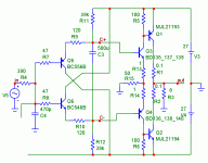
The amp shown here does not need even these 0.1ohm collector resistors, they can be omitted.
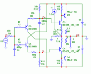
The N and P halves non-equality is a problem, that is solved by current injection into inverting input node. This is a CFB amp with voltage input and current output. I understand, it is not a traditional VFB voltage input/voltage output amplifier.
Regards,
Pavel
Pavle,
I understand that - or at least I think that I do. However, I believe that in my particular application this is an advantage, please correct me, if I am making an error in my reasoning below.
I am using a compression driver on a constant directivity horn. Such a combination results in sound pressure level corresponding to that of a plane wave measurement of the driver. Now, a plane wave measurement shows, that past certain frequency, a compression driver exhibits a monotonically decreasing sound pressure level with increasing frequency - first due to influence of voice coil inductance. At the same time, the impedance of the driver is increasing with frequency - monotonically within a portion of the operational bandwidth.
Therefore, if, as I understand it, the amplifier provides current proportional to input signal, the product of the current and the impedance will compensate the sound pressure level, due to the opposite slopes of the sound pressure level and driver impedance curves.
This is, how I modified your headphone amplifier - I am forcing a proportionality between the input signal and output current.
Kindest regards,
M
. . ., this amp has current output (in the other words, very high output impedance). That means that its output voltage changes with load impedance.
I understand that - or at least I think that I do. However, I believe that in my particular application this is an advantage, please correct me, if I am making an error in my reasoning below.
I am using a compression driver on a constant directivity horn. Such a combination results in sound pressure level corresponding to that of a plane wave measurement of the driver. Now, a plane wave measurement shows, that past certain frequency, a compression driver exhibits a monotonically decreasing sound pressure level with increasing frequency - first due to influence of voice coil inductance. At the same time, the impedance of the driver is increasing with frequency - monotonically within a portion of the operational bandwidth.
Therefore, if, as I understand it, the amplifier provides current proportional to input signal, the product of the current and the impedance will compensate the sound pressure level, due to the opposite slopes of the sound pressure level and driver impedance curves.
This is, how I modified your headphone amplifier - I am forcing a proportionality between the input signal and output current.
Kindest regards,
M
Pavel,
A clever design. Can it be satisfactorily used with full range speakers of high sensitivity, of the type used with SETs?
Given the wild impedance changes of dynamic speakers, I agree with you, but this might be suitable with very high voltage supplies for use with electrostatics, no? There are now very high voltage devices - particularly mosfets - which might be useful for the output devices.
Hi Pavel,
Good circuit. In a signal stage it can provide good linear gain as you've diagrammed, instead of driving speakers. Current sources for the top and bottom resistors supplying the inputs. Match the gains closely and connect them together thermally.
Been playing with these beasties for a few years now. It's fast, great detail and the DC offset is well controlled as configured as an output stage. I am trying to use much less bias current than you do though.
The best part is that it's simple enough to wire up and play with.
Hi Hugh,
I don't know that I would run regular dynamic speakers from a current source. Something with a smoother and predictable response might be suitable.
-Chris
Edit:
Hi Pavel,
Have you tried connecting R15 (ground side) to your output instead? I am sure you have.
- Status
- This old topic is closed. If you want to reopen this topic, contact a moderator using the "Report Post" button.
- Home
- Amplifiers
- Solid State
- Power amp with current output, F1 competitor (kidding)


