It hard to optimize a design for variable gain down to 1 by changing NFB. In non-inverting config you don't get less than unity gain, so you'd need some attenuation elsewhere. Inverting would get you close to zero but this has the drawback of lower input impedance and gain variation with source impedance.
- Klaus
- Klaus
Odd this topic should come up. I've been experimenting with something simular. I am trying varying feedback based on speaker return current. It's a way to compensate for say, a slightly mismatched passive crossover network or some compensation for a speakers resonance. This isnt the quite the same as regular current feedback. It also has another feedback loop which the voltage at the resistor in series with speaker ground adds or reduces feedback. It use the singleton input (single input trans. like the JLH style) and simply connect the negative end of the dc blocking capacitor to the speaker current sensing resistor. Attached is my expermental circuit I've been testing the past few days. This means real circuit built not just simulated. No comments on the amplifier circuit itself please, it will look quite odd and could be rambled about for some time. I am just interested in the feedback concept. Attached in this post is the circuit under test. I will show simulation examples of its behavior in following posts.
Attachments
This is the feedback voltage across the speaker current sensing resistor. I used a slightly mismatched passive crossover setup for this example. The basic concept is that this voltage is in phase with the voltage at the VAS collector which is the main feedback point. So the voltage increases the appearant feedback across R9 (the main feedback loop). So with an increase in current through the speaker results in more feedback and the gain reduced. And of course the opposite happens when you get an increase in impendance do to a resonance and the current is reduced. It will remove feedback and try to increase gain.
Attachments
AndrewT said:Hi,
I think it was Cambridge audio that did this on one of their amps.
Watch for the pot wiper going open circuit.
Yes, they attempted to fo that in the preamp section of their A1 and A100 (possibly others). Probably for fear of the pot gping open the connection wasn't really well thought out and the results were sub-par.
Here is one way to do it:
Use an inverting configuration, as this can drop gain to zero with 100% feedback.
Think of the connection as op-amp based, to get the general idea. The input of the circuit is the fully clockwise end of the pot. The output of the circuit is the tully anti-clockwise end of the pot, and is also connected to the op-amp output. The (-) input of the op-amp is connected to the pot wiper. There is also a safety resistor (*) between op-amp output and (-) input. Finally, there is a resistor in series with the input side of the pot (**).
The best op-amp type to use is a FET input amp, as you ideally need input bias current to be zero. It is possible to do it with a bipolar amp, in which case a coupling cap is needed between the wiper of the pot and the rest of the circuit.
Resistor (*) is used for safety in case the wiper goes open. It's value will normally be high compared to the resistance of the pot, and it's intended to provide default 100% feedback if the wiper cuts out.
Resistor (**) sets the maximum gain, in conjunction with the resistance of the pot and safety resistor (**). Maximum gain is Av= -(Rpot || R**)/R*. The resistor also sets the minimum imput impedance, this occurs at the maximum gain setting. At the minimum gain setting the input impedance equals R** + Rpot. Sometimes choosing the values and using an input coupling cap can be used to set a variable high-pass filter, for applications where you know it would be a good idea to progressively block subsonics as the output increases, for instance to keep your speakers alive
")
And the clincher: The pot needs to be LINEAR. The resulting characteristic will, however, be quite close to the usual logarithmic one, but with much better tracking of stereo pots, because linear taper sections tend to have quite good tracking even for cheap pots.
actually that's what's used in many preamps. it gets the potentiometer out of the signal path. i'm not a fan of having level controls or gain controls on the amp itself, since level control is the job of the preamp/mixer (IMO). amp gains in commercial equipment are usually determined by full output power at somewhere between 1 and 2 Vrms input, sometimes as high as 3Vrms. it varies from manufacturer to manufacturer, and even model to model. most manufacturers use variable level/gain controls, a few have fixed gain. i'm toying with the idea of having a variable open loop gain, since that has an effect on damping factor (unfortunately on distortion as well).
So did the 2400, and I always disconnected the switches.
In the FB loop of an opamp the pot has to be a real good one. I did a design without a cap on the wiper, and moaned when the pots began to fail.
Maybe unclejed613 will post the volume control for the APT preamp for us (altenately I could too).
In the FB loop of an opamp the pot has to be a real good one. I did a design without a cap on the wiper, and moaned when the pots began to fail.
Maybe unclejed613 will post the volume control for the APT preamp for us (altenately I could too).
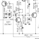
In the schematic included:
R637 is the feedback resistor from the output feeds the base
of Q605 (top left). R611 goes to ground.
If all I want [it's all about me. . . ;-) ] is to "mute" the amplifier
to a lower value without switching the input or output signal flow,
wouldn't some sort of smaller value for R637 do this. . .or would
an adjustment in R611 be required. . . kind of looks like a zobel. . .
passing highs to ground?
I took a look at the SEA designs. . .very complex circuit. . .couldn't
really tell what it was doing. . . but did see the resistors for changing
the gain of the amp and the level control.
Attachments
Yes, it can be done.gni said:. . . just was wondering if it could be done. .
and was secretly wanting it to work. . . a kind of magic solution
to silent muting.
But the feedback ratio ties in with the stability margin. You may find that each different gain setting requires a different optimised stabilty component. That would be difficult to arrange and also time consuming to find those optimised values.
Point taken.
Gotta give the Rotel a rest. . .
Need to get the M-45 back up and happy.
Yamaha Parts "couldn't find the M-45" in
their database. . .might just order a
pile of the chips and match them.
They are cross referenced to the same
ones in the RB850!
Strange. . .one amp is 50wpc and the other
is 125wpc. . . same chips -- different company.
Sanyo Vs. Toshiba
- Status
- This old topic is closed. If you want to reopen this topic, contact a moderator using the "Report Post" button.
- Home
- Amplifiers
- Solid State
- Negative Feedback Gain Control