I have just acquired a pair of ten year old working Maplin 100W amplifier modules, assembled from their late 1990s LP56L kit, each with its own independent toroidal transformer, bridge rectifier and pair of 10,000uF smoothing capacitors. The quiescent current measures about 90mA on each postive supply rail, so it is within specification.
The Antrim transformers are both rated as 160VA, 39V-0-39V (I confirmed this from the original Maplin parts list and directly with Antrim) so they ought to produce a DC supply voltage of around +/- 55V, which is also what is stated in the Maplin construction notes.
However, I am only getting +/- 47.8V on one channel and +/- 48.6V on the other. Also, there is quite obvious hum which sounds like mains ripple. And the mosfets are getting quite warm (without any speakers connected), although this may be normal.
I suspect the capacitors are not holding their charge and may be past their best - 10 years is a long time in the life of an electolytic. The four caps are incidentally marked Semcon 63V, +85C, 10,000uF.
Has anyone experienced similar symptoms? Is there anything I can do to rescue the specified performance, other than fitting new capacitors?
I did not go through any special reforming precautions, such as using of a variac to increase the supply potential gradually, but the capacitors did not seem to get hot, bulge or emit noxious fumes or anything else to suggest they were in distress.
Also, recommendations for capacitors would be useful. I have found some 10,000uF, 63V, 85C "computer grade" caps ("Suntan" brand) on the internet for only GB pounds 1.50 each (plus VAT) - from UK supplier Rapid - but that seems just too good to be without some sort of catch. Equivalent specification Panasonic caps from RS are over GB pounds 6.00 each.
Measure the supplies with the amp disconnected. What you're saying sounds about right - the capacitors have had it, simply due to the age.
I would say you are best replacing them with a bunch of smaller caps, eg 2x6800uF 63V per rail, rather than two big capacitors. High frequency performance is better this way. Look on eBay for capacitors - you will find them cheaper there.
You might also want to replace any electrolytic capacitors on the amplifier pcb's as well.
Yep if the rails are sagging that much without load, and the transformer is humming, i'd say that's definitely a sign the capacitors have dried out. You should check the transformers alone and confirm the AC voltage output is right.
The warm MOSFETs are most likely just due to the bias current. Are they mounted to a heatsink, or is this just with the L brackets ? You should probably renew the thermal paste between the MOSFETs, insulators, and L bracket at this stage.
A DC offset protection circuit is a very good idea") If it's the amps I'm thinking of, then these amps are basically a refined version of the Hitachi appnote for the original MOSFETs. There should be loads of documentation and such about them.
If it's the amps I'm thinking of, then these amps are basically a refined version of the Hitachi appnote for the original MOSFETs. There should be loads of documentation and such about them.
The warm MOSFETs are most likely just due to the bias current. Are they mounted to a heatsink, or is this just with the L brackets ? You should probably renew the thermal paste between the MOSFETs, insulators, and L bracket at this stage.
A DC offset protection circuit is a very good idea
If it's the amps I'm thinking of, then these amps are basically a refined version of the Hitachi appnote for the original MOSFETs. There should be loads of documentation and such about them.Thanks for your suggestions. I'll need to get myself an new oscilloscope or a better mutlimeter to measure the AC voltage.
The MOSFETS are mounted with what look like silpads on an aluminium L-bracket attached to the rear of a rackmount case, with dual heatsinks on the outside (probably all original Maplin specifications). They aren't getting too hot , just quite warm.
The MOSFETS are mounted with what look like silpads on an aluminium L-bracket attached to the rear of a rackmount case, with dual heatsinks on the outside (probably all original Maplin specifications). They aren't getting too hot
, just quite warm.An externally hosted image should be here but it was not working when we last tested it.
Also, there is quite obvious hum which sounds like mains ripple.
Yep, there will be mains hum. The reason is that the PCB is poorly designed; the 0v return from the output stage is routed right through the input section. I had this amp driving me nuts for ages with mains hum until someone found the problem. I built a whole series of new power supplies believing that to be the problem.
However, the good news is that there is an easy fix. What we did was hack the board a bit to separate the power connections to the input and output stages; linking and decoupling the input power rails to the output rails which is where we moved the power connections to. I have some notes and images I can post if it would help.
Once we made these changes the amp was unbelievably quiet and was much improved in every department.
Also, there is quite obvious hum which sounds like mains ripple.
Yep, there will be mains hum. The reason is that the PCB is poorly designed; the 0v return from the output stage is routed right through the input section. I had this amp driving me nuts for ages with mains hum until someone found the problem. I built a whole series of new power supplies believing that to be the problem.
However, the good news is that there is an easy fix. What we did was hack the board a bit to separate the power connections to the input and output stages; linking and decoupling the input power rails to the output rails which is where we moved the power connections to. I have some notes and images I can post if it would help.
Once we made these changes the amp was unbelievably quiet and was much improved in every department.
I'd like the information about how to improve the mains hum on the Maplin 150W Mosfet Amp....Please.
Equivalent specification Panasonic caps from RS are over GB pounds 6.00 each.
There is free p+p at RS tho.
£3-50 at Cricklewood electronics but £3-50 p+p.
Also, there is quite obvious hum which sounds like mains ripple.
Yep, there will be mains hum. The reason is that the PCB is poorly designed; the 0v return from the output stage is routed right through the input section. I had this amp driving me nuts for ages with mains hum until someone found the problem. I built a whole series of new power supplies believing that to be the problem.
However, the good news is that there is an easy fix. What we did was hack the board a bit to separate the power connections to the input and output stages; linking and decoupling the input power rails to the output rails which is where we moved the power connections to. I have some notes and images I can post if it would help.
Once we made these changes the amp was unbelievably quiet and was much improved in every department.
I can second the above!
What I did appears to amount to the same, for power supply connections I ignored the PCB pins completely and solder thick wires to the underside of the board, + and - supply wires near to the supply rail decoupler caps, 0V to a point exactly halfway between the supply cap 0V track. Use the 0V pcb pin ONLY for input signal 0V from RCA socket/volume control/whatever, no hum problems at all, much better!
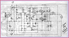
BTW... MAPLIN designer made a bit of a mistake...., the zobel resistor seen in above picture as a white block 3/7W wire wound SHOULDN'T BE wire-wound, you need a hefty 2W or more carbon/metal film or similar... a wire-wound with it's relatively high at this point negates the whole purpose of the zobel network, i.e. it is supposed to present a LOW impedance at higher frequencies...
D'oh..... who's been reading OLD posts again.....
Last edited:
Blu_glo – I hope you, and others ,keep reading old threads – it is still useful stuff for us new readers as we trawl through the forums (this is my first post).
After not picking a soldering iron for a couple of decades (afraid I have minimal theory – to be addressed) I was overtaken by nostalgia and want to finish a project I started 35 years ago. However, in true “advancing years” style, I got distracted by two Maplin 100W MOSFET kits I found in the attic.
I cleaned a faint oxide layer off the PCBs and bottoms of the TO3 cases, checked the bipolar transistors’ hfe on my multimeter, checked the MOSFETS switched on and off (thank you YouTube) and soldered away. The joints all look good but to be sure, given how long the wires have been exposed, I checked for zero resistance between the lead out wires of all directly connected components.
Being not very brave, especially after such a long pause, I first connected the amplifier to my +/- 5v supply and got a vanishingly small current drawn. I moved to +/- 15v and it is only drawing 0.8 to 1.6mA (depending on ambient temp and RV1)
A bit late, I removed and checked the 47uF (C3) as it seemed to be the only relevant electrolytic (at this stage) it measured at 49uF which suggest it has aged far better than I!
Without justification; I feel that with 15V rails I should get more current than this so I am hoping the generosity that is so much in evidence throughout this community can advise if I am just being a wimp and it will probably be fine with 50v rails or if there is something else I can check first.
That's the one - there is a clearer schematic already posted: -
http://www.diyaudio.com/forums/attachment.php?s=&postid=464052&stamp=1093640537
http://www.diyaudio.com/forums/attachment.php?s=&postid=464052&stamp=1093640537
Lets assume it is OK, so things to check (and it all sounds OK up to now).
1. Check that the DC voltage on the output (on L1) is approx zero.
2. Check that the voltage across RV1 increases as the preset is turned. Easily measured between the 100 ohm "gate stopper" resistors.
3. Turn the preset back down to zero. That is to give minimum quiescent current (and minimum voltage across RV1)
4. Test the amp with a small speaker.
When you power up on a full supply you must use a bulb tester initially. Search the forums if you don't know what one is
If all is OK then carefully set the current with RV1. This must be done finally without the bulb tester in circuit.
OK, so things to check (and it all sounds OK up to now).1. Check that the DC voltage on the output (on L1) is approx zero.
2. Check that the voltage across RV1 increases as the preset is turned. Easily measured between the 100 ohm "gate stopper" resistors.
3. Turn the preset back down to zero. That is to give minimum quiescent current (and minimum voltage across RV1)
4. Test the amp with a small speaker.
When you power up on a full supply you must use a bulb tester initially. Search the forums if you don't know what one is
If all is OK then carefully set the current with RV1. This must be done finally without the bulb tester in circuit.
scopeboy, thank you for the reassuring thought - You will understand my surprise that with 1/3 the rail voltage I was getting less than 1% of the the quiescent current. It is (proportionately) quite temperature sensitive, If I warm the L bracket with my hands the current quickly goes up by 10%, though that is just a few hundred uA
Thank you Mooly,
Voltage on L1 is 0.1mV so I guess that' easily counts
Voltage across RV1 goes from zero (of course) to 140mV
I will be taking "small speaker" very literally having just found a tiny, 64ohm specimen in my box of odd bits!
Sorry, didn't mention that in the un-annotated schematic I referenced the transistor types are different I have the original (and how) lower voltage Hitachi MOSFETs
I'm off to do step 4
I had hum problems with mine. The cause turned out to be HF oscillations in the output FETS because Maplin used 100R gate stopper resistors; just to be different. When these were increased to 220R, both the oscillations and the hum disappeared. There is an RC snubber network on the output; the hum starts when the resistor in this network burns out.
This is mentioned in another Maplin amp thread.
This is mentioned in another Maplin amp thread.
Mooly, the verdict does seem to be I am a wimp. I can't think why I didn't stick a loudspeaker across it when I had already applied+/- 15V doh. Embarrassingly I don't have a signal source to hand right now, but the sound I get from touching a finger on the input transports me back to the last time I was doing this sort of thing and the current drawn goes up to 12mA. Thank you for your gentle guidance - and I am going to research bulb-tester. I assume there is a clue in the name
johnnyx, Also thanks - I have looked at several threads that reference this amp and the gate stoppers have come up a couple of times - since they worked for you then I'll definitely be changing them - in my 15v test it was obviously oscillating if, with one finger on the input pin, I also positioned that hand right next to the MOSFETs.
Other stability suggestions I have seen are that R15 (that's part the snubber?) should not be non-inductive so not wirewound; bypass R7 with 6.8nF; and C5 and C6 can be increased to 100pF
Performance suggestions I have seen are to find a value for R9 that equalises the collector voltages on TR3 and TR5 and, in my case make the replacement 1W not my kits 0.4W; take a new zero rail return from the PCB track between the decoupling caps (9 & 11) to the PSU;
As I say, after my test result I am going to follow your suggested change immediately, Separating the 0v power return seems good practice but the rest can wait until I have the amps in their new box (almost finished) and using the proper PSU - which is going to be 51v as I have a 36-0-36 toroidal in another box!
It all sounds promising.
The bulb tester is just a 100watt mains filament bulb in series with the mains.
If the amp is built on the proper PCB's I would be surprised if there were problems tbh. That said, grounding is critical on any amp. Have a read at this and see if it makes sense because its the same layout essentially. This jumps in at the middle,
http://www.diyaudio.com/forums/soli...-lin-topology-nfb-tappings-2.html#post1624677
promising. The bulb tester is just a 100watt mains filament bulb in series with the mains.
If the amp is built on the proper PCB's I would be surprised if there were problems tbh. That said, grounding is critical on any amp. Have a read at this and see if it makes sense because its the same layout essentially. This jumps in at the middle,
http://www.diyaudio.com/forums/soli...-lin-topology-nfb-tappings-2.html#post1624677
- Status
- This old topic is closed. If you want to reopen this topic, contact a moderator using the "Report Post" button.
- Home
- Amplifiers
- Solid State
- Maplin 100W mosfet amplifier - power supply problem