Lumba Ogir said:Rüdiger,
do you have any JFETs with higher Idss, like 2N4391?
nope.
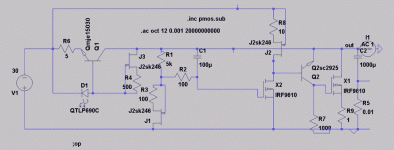
I build quite some variations from the above ciircuits and decided now to take the open loop route and trade maximum ripple rejection against low noise and better high frequency behaviour as well as smooth transient response. This design won't work too well without a preregulator of some kind, but, regarding ripple rejection, not so bad one might pense on the other hand when looking at the special 'feedthrough' for X2. Negative version for -24VDC. Q2 is 2sc2910, which I haven't a model for.
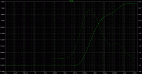
If my sim results make sense, then the attenuation is -78dB in the audioband raising to -40dB at 10Mhz. The high freq behaviour is very dependent on what you choose as ESR for the output cap in sim.
J1 must be operated at zero tempco.
Does this makes sense for you?
Rüdiger
If my sim results make sense, then the attenuation is -78dB in the audioband raising to -40dB at 10Mhz. The high freq behaviour is very dependent on what you choose as ESR for the output cap in sim.
J1 must be operated at zero tempco.
Does this makes sense for you?
Rüdiger
Attachments
I did the numbers wrong, the plot reads as attached
It's clear that this lies beneath the noise floor of anything I can think of, at least in the audio range.
How would one maintain excellent performance in physical implementation?
Since a shunt reg cuts the current loop between the load and the psu by employing a new ground return at the reg's output, one should strieve for for most quiet return. Would you think that all grounds (v-ref etc.) meet at this point or should they get a dedicated starground away from the load?
Rüdiger
Attachments
Per-Anders,
I *did* build it, and it works, however, I can't do much testing.
I pushed the regulated rail with both a 300mV and a 3Vpp sine wave at various frequencies up the Mhz-range, and while I saw no response on my scope with 300mV, I saw a tiny wiggle at 3Vpp (@5mV/div), even at small sinked currents (around 40mA).
I don't think it's too bad.
I shall tweak step response, since there is a little ringing. The sim tells it might tweaked out with good caps (much µF and low ESR).
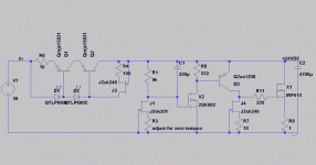
Note that I performed the sim with an IRF610 for X2 and Q2 with 2SA1206, since I don't have models for 2SK982 and 2SA1208.
Rüdiger
EDIT: and I freely admit that it's a pain to set up the v-ref properly and get the right output voltage. I would simply place a LED in J1's source *if* I had devices with large Vgs that could be matched for it with zero tc
Rüdiger
I'm just out on ideas for a good, low noise and reaonable simple voltage reference between say 20 - 40 Volts.
I want to avoid using plain ordinary zeners. So far I'm using a fet-ccs-resistor string (really a pain to spot the zero temco for a desired output voltage!) for the first stage of a phono amp, and a TL431 for the second stage reg (not shwon). Due to the high gain of the triple cfp/darlington output transistor arrangement, self noise is a concern as well as any fed-through noise of the already regulated line (a guess, because the fet-resistor seems not to perform less noisy then the TL431).
Is there anything else I can choose for a relativly high voltage vref?
Rüdiger
- Status
- This old topic is closed. If you want to reopen this topic, contact a moderator using the "Report Post" button.
- Home
- Amplifiers
- Solid State
- Simple shunt reg


