Hi,
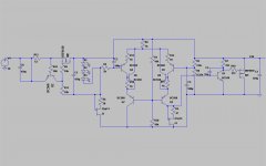
I remade the perf-board, placed 15pf between base and collector of Q1 (the driver of the shunt-Q (wich is a mosfet now) *and* put a cascode on top of the error amp. It's now stable throughout. Now I have a problem with my sope, it seems to pick up something at the highest input gain from anywhere...
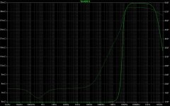
The sim indicates a output impedance of 2.8 mOhms at 1Mhz (12µthrough the audio band. Isn't that far to optimistic?
Another point is, if you really can call it 'open loop'. My understanding was, since there is no dedicated feedback path (as in a series pass reg), but the feedback goes over the V+ line, I thought about it as a kind of local feedback. What do you think it is?
Rüdiger
I remade the perf-board, placed 15pf between base and collector of Q1 (the driver of the shunt-Q (wich is a mosfet now) *and* put a cascode on top of the error amp. It's now stable throughout. Now I have a problem with my sope, it seems to pick up something at the highest input gain from anywhere...
The sim indicates a output impedance of 2.8 mOhms at 1Mhz (12µthrough the audio band. Isn't that far to optimistic?
Another point is, if you really can call it 'open loop'. My understanding was, since there is no dedicated feedback path (as in a series pass reg), but the feedback goes over the V+ line, I thought about it as a kind of local feedback. What do you think it is?
Rüdiger
Hi,
an open loop (= no feedback) design it is not.
Imagine a Zener fed Emitter Follower. It's open loop.
Your circuit monitors the output voltage across the resistor string and compares that to the fixed voltage across the LED string. It then adjusts the LTP output to control the severity of the shunt. Very much a closed loop feedback circuit.
Please post the latest schematic.
Hi Andrew,
ok, it's not simple and it's not open loop, but it's a shunt...")
It surely has feedback, but I think it is *in a way* local. Since the input and the output voltage are the same in a shunt-reg (in respect to the error amp), you don't have the output devices working in both the load and the feedback path, only in the load.
Here is the updated schematic. The cfp-input pair is meant to be an replacement for those now hard to get Toshiba FETs in respect to linearity. It additionally lowers output impedance as indicated above.
Please note, that for the moment I don't have a 2sc1775 so I used a BC550 as driver. That rises output impedance by a factor of 5 according to simulation.
Later, I will cascode the simple reg shown in the first post as well and compare them soundwise, perhaps against a super regulator as well.
Thanks,
Rüdiger
ok, it's not simple and it's not open loop, but it's a shunt...
It surely has feedback, but I think it is *in a way* local. Since the input and the output voltage are the same in a shunt-reg (in respect to the error amp), you don't have the output devices working in both the load and the feedback path, only in the load.
Here is the updated schematic. The cfp-input pair is meant to be an replacement for those now hard to get Toshiba FETs in respect to linearity. It additionally lowers output impedance as indicated above.
Please note, that for the moment I don't have a 2sc1775 so I used a BC550 as driver. That rises output impedance by a factor of 5 according to simulation.
Later, I will cascode the simple reg shown in the first post as well and compare them soundwise, perhaps against a super regulator as well.
Thanks,
Rüdiger
Attachments
but C3 and R11 don't??Onvinyl said:...C6 shall go to ground...
Wrong! I updated the schematic, see below.
The ccs itself drops very little, a few 100mV up to 150mA. The lower the Vreg in respect to Vunreg, the more.
I can't check very well in reality, because my standard r-c-r-c psu filter looses to much voltage. No real bench supply here at the moment, sadly.
Rüdiger
The ccs itself drops very little, a few 100mV up to 150mA. The lower the Vreg in respect to Vunreg, the more.
I can't check very well in reality, because my standard r-c-r-c psu filter looses to much voltage. No real bench supply here at the moment, sadly.
Rüdiger
Attachments
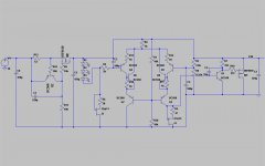
It is convenient to make R8 adjustable since there seems to be an optimum current share ratio between Q4/Q6 and Q5/Q8 in respect to regulation. It *seems* to be best to: Q4:Q6 = 1:2 -- 1:3 but I don't know why. (It regulates best in reality and has lowest output impedance in sim)
Rüdiger
Rüdiger
For your reference http://www.diyaudio.com/forums/showthread.php?postid=840668#post840668
 Shunty
Hi a,
I remember now. But my cascodes are correct! Funny, I'm just fiddling with current mirrors as in your design at the very moment.
What's wrong in my schematic is that J4 does not get enough voltage to properly act as current source.
More flaws may of course still be present.
A question rel to your noro style shunt: You use css for the diff pair; in my sim, that really screws up Zout.
Rüdiger
Onvinyl said:A question rel to your noro style shunt: You use css for the diff pair; in my sim, that really screws up Zout.
Rüdiger
As long as your master current source supply current for differential, voltage reference and at least current for shunt element=load current, your Zout will be ok.
Use Masao Noro style master current source (with M-fet if you like), size resistors around it accordingly (be sure to connect your present R11 to output, not to ground, use better voltage reference, not LED string (TL431 maybe, with J-Fet CCS and filter), your R12 should be parallel resistance of R2 + R6.
- Status
- This old topic is closed. If you want to reopen this topic, contact a moderator using the "Report Post" button.
- Home
- Amplifiers
- Solid State
- Simple shunt reg