A blocking cap in the NFB reduces DC gain to 1, a servo reduces it to virtuelly zero and no matter where the DC comes from. Plus the NFB cap is fully in the signal path (it is connected to the non-inverting input), if it has considerable inductance this will show up in the bode plot. And if it has considerable DA and sees a rather high impedance, this really becomes an issue, soundwise. I'd say a DC-servo will have more of a "not there"-quality than a cap, if it is designed carefully. Drawbacks are cost and complexity, though.
- Klaus
- Klaus
that's the bit we have to disagree on.and no matter where the DC comes from.
Compensating the DC conditions inside the power amp for external DC applied through the input is very likely to upset the carefully arranged balance and matching that we all strive for.
This is very likely to be audible.
roender, what amount of dc offset at the output is acceptable to you? And what is the open-loop dc gain of your circuit?
These answers affect your choice. The sound quality will depend upon the specific implementation of either method. A capacitor will add some distortion but so will a dc servo.
Can we assume the input signal will be dc-free?
These answers affect your choice. The sound quality will depend upon the specific implementation of either method. A capacitor will add some distortion but so will a dc servo.
Can we assume the input signal will be dc-free?
The traditional passive method invariably involves a large electrolytic in the feedback network. If you believe electrolytics are bad, than that's the worst place to put one. Any non-linearlty in the feedback network ends up in the signal. With the servo, you can arrange things to use a reasonable value polywhatever or even Teflon. Downside is complexity, stability, cost, reliability, and probably other stuff. My amps to date have used the big electrolytic, but the servo is awfully appealing. I have trouble imagining that a properly designed servo wouldn't outperform a plain cap, but the devil is in the details. "Properly designed" might be a bit more involved than first suspected.
read Tom's thread and Peranders' views for more insight to the difficulties of avoiding audibility.Conrad Hoffman said:............ "Properly designed" might be a bit more involved than first suspected.
I have heard that servos are bad for sound quality, now that I see how easy it is to get it wrong I am beginning to understand the complexity of the task, even with the experts guiding me.
Assuming no dc from the source, then good basic design and initial adjustment plus a servo would seem the rational approach to minimising output offset.
The key to servo design seems to be finding a way to inject the signal outside of the main signal path.
This method seems to work: http://headwize.com/projects/showfile.php?file=gilmore3_prj.htm
(Note to self: must read servo related threads...)
The key to servo design seems to be finding a way to inject the signal outside of the main signal path.
This method seems to work: http://headwize.com/projects/showfile.php?file=gilmore3_prj.htm
(Note to self: must read servo related threads...)
DC servo is an active part and its role is to act completely independent from amp audio function. That means all audible frequencies above 1 Hz should be outfiltered and input/output impedance of DC servo unit should be properly designed. If all these conditions are accomplished than you have to choose OP amp with some crucial characteristics to make DC servo correct, that means to servo output of the amp to exactly 0mV. All corrections of well designed DC servo unit must be unaudible and unmeasurable in all amp characteristics. If you look to major well known amp producers they all have DC servo units implementated in their amps and for good reason because all input/feedback capacitors colorate the sound of the amp no matter of the type used. Different type of capacitors are sometimes used to intentionaly corect the sound of the amp with their colorations. In my opinion ther should be no capacitor in signal/feedback path of amplifier 
traderbam said:roender, what amount of dc offset at the output is acceptable to you? And what is the open-loop dc gain of your circuit?
These answers affect your choice. The sound quality will depend upon the specific implementation of either method. A capacitor will add some distortion but so will a dc servo.
Can we assume the input signal will be dc-free?
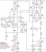
This is the front end of my amp. It has 95dB OLG and 1:40 gain (32dB)
I had tested without output stage, only with two series 1k resistors at the output of the "VAS" and with middle point connected to NFB network. The output stage will be T type AB class with 3 peers ThermalTrack devices
It has only -0.3mV DC offset, closed loop
The input signal is DC free.
Attachments
Hi,
What about neither?
I've had amps where the NFB lead is grounded directly by a resistor. In cases where the resistor value is very low, the output offset is very low too (<20mV for 4.7K/220ohm feedback).
With my recent 3886 I've used a 47uF blocking cap. I find no audible difference, if anything because of the better components and better implementation the SQ has improved (I used FC and FM caps only, and the circuit is wired P2P). As of now the offset is unmeasurable on my aging and primitive DMM.
I may try a bypass but I have kept relatively high resistor values (22K/1K feedback) which may produce about 60mV of output offset IME, since I've tried those values with an amp in the same topology earlier, and since have decided to put the cap in.
Does output offset affect the sound quality, and how?
roender said:
This is the front end of my amp. It has 95dB OLG and 1:40 gain (32dB)
I had tested without output stage, only with two series 1k resistors at the output of the "VAS" and with middle point connected to NFB network. The output stage will be T type AB class with 3 peers ThermalTrack devices
It has only -0.3mV DC offset, closed loop
The input signal is DC free.
I'll allow myself to comment a little bit your amp case. First I wonder why do you need that enourmous OLG; it's well known that OLG should be much smaller or even normal +30dB if amp has no NFB. If you'll lower OLG the open-loop bandwidth will spread over 50kHz and transient-intermodulation distorsion will be well below 100dB. If you leave OLG at 95dB you can even get unstable amp conditions at some frequencies in certain gain stages. So be careful that all gain stages have right frequency compensated impedance input/output loads.
Also that small output DC offset voltage is result of C16/C21 capacitors in NFB ground connection. Leave the caps out and you'll be surrprised in DC level at amp output.
")
I like this thread...I find myself agreeing with everyone!
It seems this is a high feedback design with very high OL gain at dc (assuming the output stage doesn't adversely load the VAS output). This means that the output offset will be dominated by the matching of the JFET gate threshold voltages. In the circuit shown there are already caps (C16, C21) in the feedback and the offset is less than 1mV. If you remove these the offset will be amplified by the feedback resistor ratio, perhaps to 40mV or so.
If you are making a commercial design you want to keep the offset below 10mV for cosmetic reasons. But for a homebrew I'd say an offset below 100mV is quite acceptable. So I'm inclined to sangram's suggestion. Build it with a real output stage, make sure the input is at 0V and measure it without the caps. Make sure you match your JFETs. If the offset is too big then put C21 back and use a non-polarized cap...a high quality one will be the least of your audible concerns. IMO it is not worth the trouble to implement a dc servo system and it is fraut with other challenges.
Hi all and thank you for your help.
I'll try to remove some confusion made by my bad english language.
LazyCat, this is not a zero negative feedback design, it has as much as possible OLG and GBW in order to make THD/IM/TIM as low as possible ...
Without C16/C21 caps to ground in feedback path, the offset is only 11mV.
I had this low offset because input jfets are well matched at IDSS and also at 6.5mA bias point. I believe that Wilson current mirror had a very much contribution at DC offset. All pairs and current sources (BJT plus LED) are thermally coupled.
So, should I remove all caps to ground and not use DC servo neither?
This is not a commercial amp and will never be, I'm only a hobbyst.
Over email exchanges with Peter I had him also concur that offset up to 100mV is perfectly acceptable for home amps.
In your case if it is only 11mV, I would say it is perfect and you do not need correction for such a small offset.
It is with values higher than 30mV that I wonder (but am not sure one way or the other) if offset is detrimental to the sound of the amplifier, since the woofer cone is not exactly centered in the spider or surround.
Having not the golden ears nor equipment to understand whether this is true, I attempt to keep the offset below 30mV - I don't why 30 and not 25 - by keeping impedances low in the input and feedback path.
Roender, I know the amp is no negative feedback design, what I meant is that you've better lower open-loop gain to reasonable 60dB, to have app. +30dB gain excess over closed-loop feedback.
It's well known, the transient and intermodulation distorsion are worse with higer open-loop gain, explanation is simple: transient has a great frequency spectrum (Feurier analysis) and separate gain stage can not follow the transient-pulse signal correctly because of high gain and poor frequency response. All spectrum signals (high harmonics components) greater than frequency response of certain gain stage are lost and the signal is therefore distorted.
The art of amp designing is to find optimum open-loop gain to determine good correlation between slew rate (high gain - amp is faster and more unstable) and transient signal distorsion (low gain - more high harmonics because of greater freq. response).
95dB of open-loop gain is not reasonable for an audio amplifier. In audiophile community 30dB of open-loop gain or no negative feedback design is more prefered, because there are more harmonics in output signal and the sound is better.
Strange, but I've found that DC-servo "kills" sound.
I prefer cap in the feedback. I'm using the highest quality ELKO available (low ESR, 105° rated, ...), bypassed with a small (10nF-100nF) foil cap.
I would suggest you to listen your design
1., with cap
2., without cap, using DC-servo
Then you'll find which one is better for your ear.
I prefer cap in the feedback. I'm using the highest quality ELKO available (low ESR, 105° rated, ...), bypassed with a small (10nF-100nF) foil cap.
I would suggest you to listen your design
1., with cap
2., without cap, using DC-servo
Then you'll find which one is better for your ear.
Dzsoni said:Strange, but I've found that DC-servo "kills" sound.
I prefer cap in the feedback. I'm using the highest quality ELKO available (low ESR, 105° rated, ...), bypassed with a small (10nF-100nF) foil cap.
I would suggest you to listen your design
1., with cap
2., without cap, using DC-servo
Then you'll find which one is better for your ear.
I think you did not design DC servo properly. There are several variables you have to consider carefuly as I explained in upper post. Well designed DC servo is unaudible; cofirmed with placebo blind tests.
May I offer a slightly different view from Lazy Cat?
The general idea is to make sure the front end of the amp doesn't apply too large an error signal too quickly to the back end. Otherwise the front end looses its linearity.
The general criteria to prevent this is to make sure the OL gain of the front end decreases with frequency, forming a slope. It's the slope that matters. Provided the slope is in the right place the gain at low frequencies needn't be capped...the gain at dc can be infinite if you want.
- Status
- This old topic is closed. If you want to reopen this topic, contact a moderator using the "Report Post" button.
- Home
- Amplifiers
- Solid State
- DC blocking cap in feedback path or DC servo?