Well friends, i need your help.
Brazil has a lot of “do nothing” things
beeing sold...we use autotransformer (1 single coil) having electronic switching of
relays to control the AC voltage...called AC voltage stabilizers...has coil tapes of
100, 120 and 140 volts ... so... senses the
main voltage and goes compensating the mains voltage fluctuations.... in the reality, our mains do not fluctuate this way.... the sutotransformer introduces losses, and it is compensating, correcting, his own losses to be a coil in seriew with mains voltage...a do nothing.
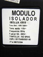
Now appeared an “insulator”... a simple transformer having two wires secondary to 120 volts and the primary is switchable from 120 to 240 volts.... this intends to produce you output having ground when you home has not ground..artificial ground or something alike... you can invert and not problem...the input use 2 pins plugs and the output uses the standard three pins plug having ground.
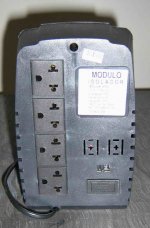
I have not ground in my new home..a more old and simple building....because of that a friend gave me that thing..enormous..having a heavy weigth transformer inside the case...you will see images.
This had not power to face my computer and the monitor refuses to work....so.... power is not so big as i was thinking.
I am thinking to use it in series with other transformers to have other voltages..but i have doubts about the power result.
Can you explain me the result of the image provided...the power expected?
Thank you in advance by the kindness to explain me that.
regards,
Carlos
Brazil has a lot of “do nothing” things
beeing sold...we use autotransformer (1 single coil) having electronic switching of
relays to control the AC voltage...called AC voltage stabilizers...has coil tapes of
100, 120 and 140 volts ... so... senses the
main voltage and goes compensating the mains voltage fluctuations.... in the reality, our mains do not fluctuate this way.... the sutotransformer introduces losses, and it is compensating, correcting, his own losses to be a coil in seriew with mains voltage...a do nothing.
Now appeared an “insulator”... a simple transformer having two wires secondary to 120 volts and the primary is switchable from 120 to 240 volts.... this intends to produce you output having ground when you home has not ground..artificial ground or something alike... you can invert and not problem...the input use 2 pins plugs and the output uses the standard three pins plug having ground.
I have not ground in my new home..a more old and simple building....because of that a friend gave me that thing..enormous..having a heavy weigth transformer inside the case...you will see images.
This had not power to face my computer and the monitor refuses to work....so.... power is not so big as i was thinking.
I am thinking to use it in series with other transformers to have other voltages..but i have doubts about the power result.
Can you explain me the result of the image provided...the power expected?
Thank you in advance by the kindness to explain me that.
regards,
Carlos
Attachments
Transformer inside is huge... enormous type of transformer, traditional construction E plates and I plates trafo.
Secondary over the primary layers.
The size seems to be a 1.2 Kilowatt transformer...very big.
But specified as 300 VA..... and made sense to me when testing.... real power is not big.
Bad design i think...that iron could produce much more than 300 VA.
Here is one image.
regards,
Carlos
Secondary over the primary layers.
The size seems to be a 1.2 Kilowatt transformer...very big.
But specified as 300 VA..... and made sense to me when testing.... real power is not big.
Bad design i think...that iron could produce much more than 300 VA.
Here is one image.
regards,
Carlos
Attachments

Well, the unit was made with the purpose to "create" a ground to you
And to protect your computer against main plug invertions...as the wall have two pins and the plug has three...people use to remove the ground and inject those two pins into the wall.
This produces some problems, i imagine, as one of those wall pins is 220 alternated (Live, Phase)...and the other is neutral (Zero, return)
The unit has 2 pins plug into the input and 3 pins into the output.
It could not feed power enougth to my Sempron 3 Megahertz together my power audio amplifier (class D) and my electron tube monitor, the conventional Samsung.
The supply could not keep the voltage stable enougth...had losses of voltage.
So...this "do nothing" thing will not be used into my computer.
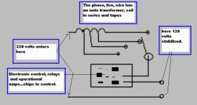
I am trying to use it to audio...maybe... and needing informations about the power i will have...watch the sketch i have made showing two transformers and help me, please.
regards,
Carlos
And to protect your computer against main plug invertions...as the wall have two pins and the plug has three...people use to remove the ground and inject those two pins into the wall.
This produces some problems, i imagine, as one of those wall pins is 220 alternated (Live, Phase)...and the other is neutral (Zero, return)
The unit has 2 pins plug into the input and 3 pins into the output.
It could not feed power enougth to my Sempron 3 Megahertz together my power audio amplifier (class D) and my electron tube monitor, the conventional Samsung.
The supply could not keep the voltage stable enougth...had losses of voltage.
So...this "do nothing" thing will not be used into my computer.
I am trying to use it to audio...maybe... and needing informations about the power i will have...watch the sketch i have made showing two transformers and help me, please.
regards,
Carlos
Attachments
Using switchmode powersupply must be nice in that situation?.. Most computers have already wide input voltage range?..
Hmm seems like my amps would work perfectly there :-D using wide input range vicor switchmodules (But they can be a bit expensive)..
But an answer to your question I have not.. just more questions..
About earth, couldnt you just drive down a long metal rod into the ground and use as earth? hmm ;-) hehe
Yes Nikwall... switching supplies are better...but i have that monster to use
I do not want to make it as junk, to use as a feature to block my door against be shutted because of the wind...not as paper weigth too...ahahahahahaha
I can use the copper rod....but.... building rules, laws, agreements already made, do not let us run wires into the front of the building...nor the back, nor the sides.
So...i can have the rod..the ground..but not the connection to reach my appartment.
The electrical system has a small diameter tube to run another wire together the others already into a tigth space.
Well, my dear, this is third world...thing here are bureaucratic, bad constructed and agreements are very complicated.
But thanks, anyway...at least we had a good social meeting.
regards,
Carlos
Attachments

I just come to think of it.. We use insulation transformers at work on the testbenches for reparing electronics.. It's quite strange, the old transformers from ASEA sweden are big fat azs things rated at almost no power, and there are also small ones made elsewhere that look rediculus rated at too high power to be safe.. I think it has to do with different rules in different countries how to specify when its "safe" hehe
As i told you..we have the old tradition to use the "do nothing"
things.... television aerials that do nothing... looking alike a spacecraft and doing nothing.
Almost all population that uses computers....maybe 80 milions, use the AC voltage stabilizer.
Someone create that idea, and others follow...millions using and they do not know why....they just know that others use..then....may be needed... if may be needed, so...let's use it.
Those fooling things are around us...and this one is the biggest do nothing thing.
You see...i am using..ahahahhaha...everybody use...ahahahahha.
regards,
Carlos
Attachments

The autotransformer everybody uses here
Works fine...do not disturb too much, only the annoying click of the relays.
The one i use is a real 700 watts unit.
Of course the computer works fine without that thing, because the supply is a switching one and works better than those things.
Gimmick...do nothing...unobtanium.... but it is very cheap...that unit cost 20 dollares only!
regards,
Carlos
Attachments
I have asked Santa Klaus..... to the Christmas... a nice
17 inches, brand new LCD from Samsung.
I will have it...hehe..this monster here will receive a shot into the screen....
No!.... i will give it to the nearest school.
Image is Dx, the monster, trying to kill the monitor...hehe..kiding, of course, i use to destroy amplifiers only.
regards,
Carlos
17 inches, brand new LCD from Samsung.
I will have it...hehe..this monster here will receive a shot into the screen....
No!.... i will give it to the nearest school.
Image is Dx, the monster, trying to kill the monitor...hehe..kiding, of course, i use to destroy amplifiers only.
regards,
Carlos
Attachments

Hey folks!.. i need the information... what will be the power
I will have connecting those transformers.
Watch the sketch and help, please!
regards,
Carlos
...................................................................................................
Nico
You have a good photo camera, the digital camera...send images to my adress dear Nephew.
panzertoo@yahoo.com
regards,
Carlos
Attachments

Re: Well, the unit was made with the purpose to "create" a ground to you
When plugging three pronged items into two prong outlets, I sometimes used to verify which should be the neutral just to be safer.
Your transformer may have originally have been for another purpose, using, for example, 220 and 440 volts. Ya just have to be careful about doing that. I do it all the time because I am naturally a trend-bucker. Thorough testing is good, then, like you are doing.
destroyer X said:
And to protect your computer against main plug invertions...as the wall have two pins and the plug has three...people use to remove the ground and inject those two pins into the wall.
This produces some problems, i imagine, as one of those wall pins is 220 alternated (Live, Phase)...and the other is neutral (Zero, return)
The unit has 2 pins plug into the input and 3 pins into the output.
It could not feed power enougth to my Sempron 3 Megahertz together my power audio amplifier (class D) and my electron tube monitor, the conventional Samsung.
The supply could not keep the voltage stable enougth...had losses of voltage.
So...this "do nothing" thing will not be used into my computer.
I am trying to use it to audio...maybe... and needing informations about the power i will have...watch the sketch i have made showing two transformers and help me, please.
regards,
Carlos
When plugging three pronged items into two prong outlets, I sometimes used to verify which should be the neutral just to be safer.
Your transformer may have originally have been for another purpose, using, for example, 220 and 440 volts. Ya just have to be careful about doing that. I do it all the time because I am naturally a trend-bucker. Thorough testing is good, then, like you are doing.
Well Carlos I think that the power of the whole circuit is determined by the first transformer. No matter how big your second transformer will be, the first one is the bottleneck. So your overall power capability will be power of the first transformer. That's my point of view ")
after: Conservation of energy rule
regards
ostry
after: Conservation of energy rule
regards
ostry
Thank you electrone..... also thanks to Ostry
Yes Ostry, this was what i was thinking about...... and now i am thinking this way with more belief.
The weakest piece of a chain will decide how strong will be that chain.
This is clear to me too.....my doubt Ostry, will i have more losses using another transformer core?
Can i have lower power than the one provided by my first transformer?
I think will be a good idea to test, in a real world, to put things to turn hot and red... the way electron does.
regards,
Carlos
insulating transformers have a lot of losses because they need not to transfer everything from primary to secondary - that is why they do not transfer spikes in the mains supply and can be used as filters....this is not bad designing but designing for a purpose....so Carlos you have that low power on the secondary because you have a lot of losses in that thing...
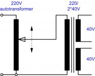
i would not use that transformer for the purpose that you want and is specified in the mail no.1.....better option is to use rotary autotransformer that you can change the output voltage from that transformer and than to feed that output to your power transformer that you have ... and instead of using that one that has 2*27V you can use one that has for example 2*40V at the secondary and adjust the voltage to your needs on the autotransformer...like in the picture...
i would not use that transformer for the purpose that you want and is specified in the mail no.1.....better option is to use rotary autotransformer that you can change the output voltage from that transformer and than to feed that output to your power transformer that you have ... and instead of using that one that has 2*27V you can use one that has for example 2*40V at the secondary and adjust the voltage to your needs on the autotransformer...like in the picture...
Attachments
Thank you Sparkle and Ostry.
I already decided, i will dismount and rewound it to 63 plus and 63 minus.... having another coil that will result in 66 plus and minus after rectification and filtering.
The unit is huge....and i will try this more traditional way...because of those losses U2 said.
regards,
Carlos
I already decided, i will dismount and rewound it to 63 plus and 63 minus.... having another coil that will result in 66 plus and minus after rectification and filtering.
The unit is huge....and i will try this more traditional way...because of those losses U2 said.
regards,
Carlos
Hi D,
re that first post wiring diagram.
The first transformer gores from 220 to 54Vac when loaded to 350VA (~6.5A).
The second transformer when wired back to front gives 1:1 or 1:2.
If you feed full voltage into the secondary you will get full VA from the secondary. But if you feed 54Vac into the 120Vac secondary then the maximum output is roughly halved. If it started out as a 1000VA then you will have ~500VA as maximum throughput.
The power you can draw from the pair will be limited by the smaller VA i.e.350VA.
The voltage at the output will be 54Vac or 108Vac.
However, there is an alternative.
The 350VA transformer isolates the mains from the output.
It is safe to wire up the second transformer as a step up auto transformer. Feed the 54Vac into the ~8A, 120Vac secondary.
Wire one of the primaries (~4A 120Vac) in series with the secondary and you get double voltage out of the pair of windings.
Add the second primary and you will get triple the voltage out of the three windings in series. You now have three voltage tappings 54Vac, 108Vac and 162Vac, all at 350VA.
There are probably a few more ways to wire this arrangment up.
But, do keep at least one transformer as the mains isolation, it can be either the first or the second, the order does not matter.
- Status
- This old topic is closed. If you want to reopen this topic, contact a moderator using the "Report Post" button.
- Home
- Amplifiers
- Solid State
- Electrical Engineers!... i need information..help old Dx, please!