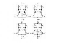
Hi, Borbely often uses this cascode: Figure 7 in this document
Some have wondered, which advantage this might have, because you then get the penalty of very low Vds, so one would normally opt for a explictly biased gate.
But is this method not more quieter than any activly biased solution?
Rüdiger
Some have wondered, which advantage this might have, because you then get the penalty of very low Vds, so one would normally opt for a explictly biased gate.
But is this method not more quieter than any activly biased solution?
Rüdiger
Hi Onvinyl,
I think Borbely uses that arrangement due to convenient DC biasing, circuit simplicity and predilection for J-FETs.
The way J-FETs can be biased is not just elegant but advantageous, less contaminating, so very explicit to me. Voltages applied to any sensitive gate or base, as of the cascoding device, should be kept clean, free from ripple and noise, as it would be amplified and mixed with the audio signal. It is not that easy to accomplish for bipolars and MOSFETs all the time.
I am a little bit curious to know your opinion: what would be the penalty of very low Vds?
Hi Lumba,
thanks for your reply.
Well, for one part my current sk246 have a to small Vp, so the Vgs in operating conditions was too small to let the cascoded FET work.
And I think, since the Srin of the upper FET is small, but not 0, you need a very small area were a tiny voltage swing can take place.
Third, but that may as well be an advantage, the gate of the upper fet is not silent, but fed with signal from the source of the cascoded FET. But since it's opposite phase to the source of the upper FET, it may apply a kind of local feedback, which might be useful. But anyhow, the cascoding FET ist not in grounded gate mode, strictly speaking.
Rüdiger
Hi Rüdiger,
I might miss your point... but I see both stages, 1st and 2nd, as true cascodes, trying to keep Vds of the cascoded FETs constant. The second stage uses a higher Vds which is generated by offsetting the cascoding FET with a zener. Maybe its not actually higher but just acounts for the different threshold voltages of the cascoding FETs.
Actually he uses -- and has to use -- LM336 5V-references in the final circuit, where he cascodes with enhancement mode MOSFETs with positive threshold -- but draws symbols for depletion mode MOSFETs .
.
To have the cascoded FET running well above the knee Vds voltages one can use a FET (for the cascode-T) with high negative Vgs(th) and/or offset its Vgs(th) .
Nelson Pass has elaborated on cascode modulation, that is, making the Vds not precisly constant but signal dependent to smooth out part of the nonliearity of the transfer function. Ids increases with Vgs but decreases with Vds so that one might find a point where one gets some useful cancelling. That modulation would happen here if the Zeners went to the supplies, not to the sources.
Something similar happens when the Vds is in the region of the knee voltage, which shifts to the right with increasing Vgs. Quite dependent on and very sensitive to actual device characteristics...
- Klaus
I might miss your point... but I see both stages, 1st and 2nd, as true cascodes, trying to keep Vds of the cascoded FETs constant. The second stage uses a higher Vds which is generated by offsetting the cascoding FET with a zener. Maybe its not actually higher but just acounts for the different threshold voltages of the cascoding FETs.
Actually he uses -- and has to use -- LM336 5V-references in the final circuit, where he cascodes with enhancement mode MOSFETs with positive threshold -- but draws symbols for depletion mode MOSFETs
.To have the cascoded FET running well above the knee Vds voltages one can use a FET (for the cascode-T) with high negative Vgs(th) and/or offset its Vgs(th) .
Nelson Pass has elaborated on cascode modulation, that is, making the Vds not precisly constant but signal dependent to smooth out part of the nonliearity of the transfer function. Ids increases with Vgs but decreases with Vds so that one might find a point where one gets some useful cancelling. That modulation would happen here if the Zeners went to the supplies, not to the sources.
Something similar happens when the Vds is in the region of the knee voltage, which shifts to the right with increasing Vgs. Quite dependent on and very sensitive to actual device characteristics...
- Klaus
This is an interesting design, and almost ideal. Its biggest limitation is selecting the parts to do it right. People seem to have such a problem with just getting ANY complementary parts, that getting the best parts for this circuit might be a real problem.
The two types of jfet cascode biasing are well known. Usually for the first stage, you use a cascode part with low Gm, but high Idss. This allows a small voltage across the input part, that makes it behave better.
In this case, Borbely uses a voltage source with the second stage part, (just like I do in my new Parasound JC-2 preamplifier). This is a more 'linear' approach, but it does involve more parts and their potential noise contribution.
I use to hate j-fets back in my ignorance, but I have learned to love them. Wouldn't build an amp without them.") In the case of the input cascode device, a lower Gm higher Idss part usually has a greater Vgs @ Id. It is important to keep the Vdg greater than Vgs on the source j-fet feeding it.
In the case of the input cascode device, a lower Gm higher Idss part usually has a greater Vgs @ Id. It is important to keep the Vdg greater than Vgs on the source j-fet feeding it.
I wish j-fets were more popular by large scale manufacturers, and then there might be some real demand to create and make many different types available, especially matched duals.

In the case of the input cascode device, a lower Gm higher Idss part usually has a greater Vgs @ Id. It is important to keep the Vdg greater than Vgs on the source j-fet feeding it. I wish j-fets were more popular by large scale manufacturers, and then there might be some real demand to create and make many different types available, especially matched duals.
Hi Rüdiger and Klaus,
In my view: the nonlinearity of JFETs is mainly caused by high and varying internal capacitances.
Linearization can effectively be made by keeping certain parameters, like Vds and Ids CONSTANT.
Borbely has obviously special liking for JFETs and other FETs, however, the cascoding device should be bipolar, maybe (discretely made) Darlington.
Lumba Ogir said:the cascoding device should be bipolar
This has been my choice for many years. Based solely on good results and to many other things to try. Can you elaborate?
Regards, Mike.
Lumba Ogir said:however, the cascoding device should be bipolar, maybe (discretely made) Darlington.
Hi Lumba,
do you have an example circuit for a FET - darlington transistor assemble as cascoding Q?
Rüdiger
Mike,
the best suitable types would be high voltage devices, devices intended for video applications with very low Cob handling large voltage swings superbly. The same kind of transistors which should be used in VAS for heavy voltage amplification and driving. FETs do not perform well here for some reason. It is about transconductance too, I suspect.
the best suitable types would be high voltage devices, devices intended for video applications with very low Cob handling large voltage swings superbly. The same kind of transistors which should be used in VAS for heavy voltage amplification and driving. FETs do not perform well here for some reason. It is about transconductance too, I suspect.
Rüdiger,
well, our taste are different.
http://www.diyaudio.com/forums/showthread.php?s=&postid=1282639#post1282639
A circuit with some complexity, in post #44
well, our taste are different.
http://www.diyaudio.com/forums/showthread.php?s=&postid=1282639#post1282639
A circuit with some complexity, in post #44
MikeBettinger said:
This has been my choice for many years. Based solely on good results and to many other things to try. Can you elaborate?
Regards, Mike.
I use to make input stages with 2sk170 (BL or V) cascoded with 2sc3423 (cob 1.8pF) at 14mA tail current.
It sound a little bit better than 2sk170 cascoded with 2sk246
IMMV
Lumba Ogir said:
Borbely has obviously special liking for JFETs and other FETs, however, the cascoding device should be bipolar, maybe (discretely made) Darlington.
Lumba, this was the tip of the day. simmed a folded cascode made of an discrete sziklai pair, simms great.
Now I have to look if it works in reality equally well.
Rüdiger
Onvinyl said:
Lumba, this was the tip of the day. simmed a folded cascode made of an discrete sziklai pair, simms great.
Now I have to look if it works in reality equally well.
Rüdiger
Where did you put CFP pair? In common base transistor place, folded cascode design?
FC works very well if you use current sources instead resistors in series with BE cascode transistors.
- Status
- This old topic is closed. If you want to reopen this topic, contact a moderator using the "Report Post" button.
- Home
- Amplifiers
- Solid State
- Borbely Cascode