Dear All,
As a new boy to the forum, i would like to gain some opinion as to what has the most significant affect on the deepest bass and general listener fatigue on a power amp using a MOSFET O/S.
I am using 5 pairs of magnatec single die plastic FET's per chanel with matched (within a few %) VGS on. The FET are used in the 'enhanced mode'.
The PSU has tightly regulated rails, +/-70, +/-35V and + and - 10V (with respect to the 70's) for enhancing the FET's.
Input stage and VAS are similar to self's blameless amplifier.
The main area of interest to me at this moment is the configuration of the O/S and views on O/S feedback.
Any thoughts on the above would be appreiciated.
Cheers
Sheriff
I do not know for certain which can give deep bass.Sheriff said:Dear All,
As a new boy to the forum, i would like to gain some opinion as to what has the most significant affect on the deepest bass and general listener fatigue on a power amp using a MOSFET O/S.
I am using 5 pairs of magnatec single die plastic FET's per chanel with matched (within a few %) VGS on. The FET are used in the 'enhanced mode'.
The PSU has tightly regulated rails, +/-70, +/-35V and + and - 10V (with respect to the 70's) for enhancing the FET's.
Input stage and VAS are similar to self's blameless amplifier.
The main area of interest to me at this moment is the configuration of the O/S and views on O/S feedback.
Any thoughts on the above would be appreiciated.
Cheers
Sheriff
And to know what gives less listening tiredness
I wouldn't think anyone knows really.
-------------
Bass needs a good PSU - not too small transformator.
To limit the upper frquency could eventually
give a "softer" sound. And that could possibly make you less tired of listening.
--------------
Think you are to build a quite good amplifier.
You have good knowledge, and the details
will be worked out.
Make a first version. Then test and listen.
Then you can make changes and trim with capacitors.
You will get good advices here.
/halo - watching an amplifier being born
")
Halo, the story so far...
OK Halo,
The PSU works really well.
It is a PFC based half bridge switcher using current mode control.
I have synchronised the PFC, downconverter and aux supplies to avoid beat frequencies.
Ripple and noise is very low for a supply of this type and the thing well shielded, power limit is 1600W- a good start.
There has been a lot of people playing around with open loop output stages, but i would imagine the THD etc to be poor.
Maybe some kind of forward error correction a la hawkesford should be in order.
Caps are another interesting one. the closed loop switcher gives a very low output impedance, and quick refreash rate (70KHz) but i will play around with the value of the caps on the amp board. I have heard that the 'gold tune' nichicon electrolytics are pretty good. Have you any experience with these?
This should be ok as the PSU loop stablity will increase if i up the C a bit (800uF decoupling close to the MOSFET's per rail currently)
Just after some comments on what people have tried, kind of correlating opinions really.
Cheers
Sherrif
okay
PFC, I have never heard of that name.
But I understand it is a switching power supply thing.
--------------------
I have never used any other Caps then ordinary Elyts.
Rifa and ROE.
I think the value is more important than the Letters on the Label.
But those small caps we need to put into an amplifier,
at the last trimming, is what I am thinking of.
Compensation and such. It can of course involve some decoupling, too.
-----------------------
In many MOSFET output stages, I have seen fairly large Caps
Next to the transistors. Like 1000uF.
So I think that is a good idea.
------------------
I am right now searching the web.
To find out about Malcolm Hawksford (without "e"!!!).
He seems to have done some research about high speed digital
cables. I do not know if this can be used for Low Frequency Audio applications.
But any knowledge is good.
This is attributable to the intermodulation of Sonic's master clock by signal-correlated jitter during the loadin. During playback, since the source is no longer feeding digital audio, even though the DAW is still locked to the external clock, the external clock is much more stable from the DAW's point of view. Its PLL is no longer modulated by the digital audio that is combined with the external clock. This well-known phenomenon, known as signal-correlated jitter, has been documented by researcher Malcolm Hawksford. See AES preprint titled "Is the AES/EBU S/PDIF Interface Flawed" AES Journal 1995. This form of jitter is quite audible.
/halo - is hungry - should have something to eat now
PFC and FEC
Hi Halo,
M Hawksford, developed a forward error correction stage for MOSFET output stages.
Reducing distortion of this stage to as little as .008% i recall.
Sorry, PFC stands for power factor correction. Where the PSU takes energy from the mains through about 90% of the cycle rather than just grabing current from mains 50 or 60 times a second. The PSU presents a pretty constant resistive load to the mains.
The PSU drawing from the mains on a near continous basis is pretty cool for audio and runninf an amp in areas where the mains conditions are poor.
Again, any help is gratefully received.
Thanks
Sheriff
Re: PFC and FEC
Tandberg and Akai (not in US market) released amps using Hawksford's output stage error correction tech. I never heard them but the schematics were fun to study.
mlloyd1
Tandberg and Akai (not in US market) released amps using Hawksford's output stage error correction tech. I never heard them but the schematics were fun to study.
mlloyd1
Sheriff said:...
M Hawksford, developed a forward error correction stage for MOSFET output stages.
...
Sheriff
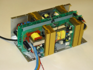
The PSU
Hi Sam,
The PSU started life as a forward converter, it has been developed into this. It is of our own design.
I have a picture if anyone is interested.
It has taken a long time and a lot of $$$ to develop.
But the results are worth it. (thank god...)
The FEC stuff has been used in a few commercial designs that i know of like the halcro units.
Cheers
Sheriff
Here is a 1600W low-noise PFC PSU
PFC MegaPAC-EL (Low Noise) AC-DC and DC-DC Power Supplies
(Noise and Ripple: <10mV p-p or 0.15%, whichever is greater)
Number of outputs: 1-16 (8 slots)
Input voltage: 85-264Vac, universal, PFC; Max output power: 1600W
Size: 15.5 x 6.0 x 3.4 in; 393,7 x 152,4 x 86,4 mm
PFC MegaPAC-EL (Low Noise)
/halo
Attachments
It is when you easily get tired of listening a long time.MRehorst said:What is "listener fatigue"?
MR
Some soundsystems you can listen a long time
without wanting to Turn OFF.
This is what they say in the reviews.
/halo
Malcolm Hawksford Publications
Error correction in amplifiers is from 1981.
He seems to have done work in all about analog/digtal signaling.
Even Loudspeaker phase correction.
Malcolm Hawksford Publications - Audio Research Laboratory Department of E.S.E. University of Essex
/halo - not that many publications, yet
-------------------------------------------------------------
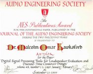
Picture:
Hawksford gets AES Publication Award - September 2000
Here is a list of Malcolm Hawksford publications 1971-2001.capslock said:Actually, I'd be more interested in the feed forward error correction. Anybody got a link or schematic? Thanx, Eric
Error correction in amplifiers is from 1981.
He seems to have done work in all about analog/digtal signaling.
Even Loudspeaker phase correction.
Malcolm Hawksford Publications - Audio Research Laboratory Department of E.S.E. University of Essex
/halo - not that many publications, yet
-------------------------------------------------------------
Picture:
Hawksford gets AES Publication Award - September 2000
Attachments
- Status
- This old topic is closed. If you want to reopen this topic, contact a moderator using the "Report Post" button.
- Home
- Amplifiers
- Solid State
- Thoughts on a mosfet amp with low listener fatigue and full, deep bass??