I am using a two channel Leach 4.5 that I built some time back. I plan on building a pair of speakers and want to bi-amp instead of using active crossovers. My plan is to drop Q18 and Q19 on the two existing amps, add two more Leach amps (without Q18 and Q19) and use the original heat sinks. Each heat sink will handle two amps and contain two pairs Q20/Q21 with four bias diodes between each (ah-la Leach). Each heat sink is currently set up, top to bottom, Q18-Q20-4BD's-Q19-Q21. What I propose is Q20-4BD's-Q21-Q20-4BD's-Q21. Can anyone share experience or ideas about this arrangement? I want to do this because my chassis layout prevents addition of two more heat sinks and I probably will not need the added power. Any thoughts here would be appreciated, thanks.
There is a reason why bi-amping without an electronic crossover is called 'fool's bi-amping'.
What you seem to be proposing seems very foolish. If you reduce the number of outputs to two per channel you will need to lower the supply voltage too (to about ±42V).
If you want to make the Leach sound better, add a regulated supply for the voltage gain stages.
What you seem to be proposing seems very foolish. If you reduce the number of outputs to two per channel you will need to lower the supply voltage too (to about ±42V).
If you want to make the Leach sound better, add a regulated supply for the voltage gain stages.
djk - thanks for your helpful reply; do you have any hobbies outside of this page?
I have built ESP's electronic cross over.
According to Leach's recommendation, the rail voltages should not be less than 50V when dropping Q18 and Q19.
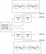
My question relates to using one heat sink to handle two output pairs, one from each amplifier and if it would be acceptable to use two sets of diodes to bias. Here is schematic of what I am talking about -
I have built ESP's electronic cross over.
According to Leach's recommendation, the rail voltages should not be less than 50V when dropping Q18 and Q19.
My question relates to using one heat sink to handle two output pairs, one from each amplifier and if it would be acceptable to use two sets of diodes to bias. Here is schematic of what I am talking about -
Attachments
Hi,
there ia no reason that two output stages could not share a common heatsink.
It is commonly done with stereo amplifiers.
All you propose is two stereo amplifiers in the same case.
But, do make sure that the heatsink is capable of dissipating sufficient heat to keep both output stages cool when operational.
I suspect that Rth s-a for the two channel sink should be less than 0.5C/W (i.e. <=1C/W for each single pair output stage running @ Ib=75mA).
Do realise that 1pair of 250Vce0 devices (ML21193/4) on +-58Vdc can drive a severe 8ohm speaker load very well, but cannot manage to drive even a moderate 4ohm speaker.
I am confused by your statement
and your diagram showing active crossover prior to the four amplifiers. This looks like an active speaker system.bi-amp instead of using active crossovers.
That was my bone headed mistake, I did mean passive cross-over. Now I understand djk's ire! Sorry djk.
The heat sinks currently have are rated 0.5 deg C / Watt.
I want to keep the cost of this little upgrade down and hence don't want to change the power supply as djk suggests (though this may not be possible). If I understand correctly, driving a too low impedance load minus Q18/19 would put Q20/21 in over current condition? Would there be anything I could do on the speaker side to ensure sufficient impedance? Maybe the most cost effective way would be to regulate down as djk said.
I kind of have this obsession about building an amp incorporating a PC for media storage and play back. I keep running up against enclosure size. To stay in typical chassis dimensions it is difficult to squeeze a micro atx board inside. It gets more complicated with bi-amping if four heat sinks are used. This build I'm working on now and is slated for nano ITX main board. I want to stack the two additional Leach-4.5's on the existing ones and use the same heat sinks as discussed.
Attachments
Hi,
are your speakers described as 4ohm, or 6ohm, or 8ohm, or 4 to 8ohm?
Have you tried measuring the driver resistances?
These will give you a good clue to whether your proposed change is feasible.
The outputs will be more stressed if 1pair are asked to do the duty of a 2pair design.
However, much of this extra stress is removed by increasing the minimum impedance to the 8ohm level.
If the impedance is lowered, not only are the output devices more highly stressed but the drivers and pre-drivers also see the effect particularly since the output device gain falls with increasing current. You may find that the output device current doubles when the speaker impedance is reduced from 8ohm to 4ohm. The driver however may see a three fold increase in current for the same change and the pre-driver could suffer a four fold increase.
If any of the devices you originally chose for these locations/duties are close to their limits either due to operating temperatures or inherently low SOA then any one of these could fail by removing two of the output devices and asking the amp to drive a lower than accetable load impedance.
Stick to 8ohm and you should be OK.
Your right ...
That spec is for forced 250 liters/min air flow. For natural convection Wakefield publishes 47 C @ 50 W. These sinks have worked fine for my two channel set up so far.
I have not purchased the speakers yet, but will make sure they are nominal 8R.
How do you calculate the current through the ops transistor given the supply rail voltage and speaker load?
- Status
- This old topic is closed. If you want to reopen this topic, contact a moderator using the "Report Post" button.
- Home
- Amplifiers
- Solid State
- Bi-Amp / Leach / Ops Transistor Heatsink Arrangement