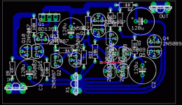
I was experimenting with different regulators in Spice, and I came up with two versions. The first one is based on the POOGE regulator. The design is somewhat different, some values have been changed, and I use two transistors as a voltage reference. They are much quieter than zener diodes, and the small reference means that it can work well even at very low voltages. The parts for this regulator costs around $3, which is about the same as the original POOGE regulator.
Schematic is attached, I used transistors instead of diodes to simplify things.
Schematic is attached, I used transistors instead of diodes to simplify things.
Attachments
The second regulator is a cross between the POOGE and Walt Jung's super regulator. I use two transistors as a reference here as well, but I replaced the op amp with discrete components. I did not know how this would affect the performance, I mainly did this to lower the cost. The entire regulator can now be built for around $5.
Attachments
Attached is a simulation comparing the performance of various regulators. Green is an LM317, blue is an LT1085, red is the POOGE regulator found on ALW's website (here), cyan is my POOGE regulator, pink is the Sulzer regulator (with NE5534), dark green is the latest version of Walt Jung's super regulator (with preregulator and AD825), and orange is my super regulator.
Note that my POOGE regulator outperforms the Sulzer regulator and even rivals the Jung regulator at higher frequencies. Because of the low cost you can easily run two of them in series, this would lower the noise floor to below -200 dB. My super regulator performs around 60 dB better than my POOGE regulator, and running two of them in series would lower the noise floor to well below -300 dB.
Note that they are only simulations however, and as such they should be taken with a grain of salt. If anyone wants to build these be my guest.
Attachments
")
If only life were that easy!you can easily run two of them in series, this would lower the noise floor to below -200 dB. My super regulator performs around 60 dB better than my POOGE regulator, and running two of them in series would lower the noise floor to well below -300 dB.
Unfortunately it isn't; you'll find that in real life you'll struggle to get below -120 to -130dB. All sorts of reasons why, all of them parasitic terms.
chalkandtalk[/i] [B]However said:Any broad voltage and current limit numbers?
That depends on the pass transistor. I chose a BD139 in the schematic above, but almost anything will work. The same applies to the small signal transistors. I chose 2N5087 and 2N5089 as they are common, but almost anything will work here as well. BC550 and BC560 might be easier to get ahold of in Europe.
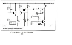
awpagan said:Or another very simple but effect circuit
by John Lindsay Hood
Something is missing there. This circuit will not regulate.
Hi,
any small signal transistor will do.
As suggested the bc550c/560c or for more Vce0 bc546c/556c will be admirable.
A few devices should be matched.
It would be very worth while reading Pooge and Jan Didden (our Janneman) and Jung to understand how and why these circuits work to ensure the PCB is laid out correctly. I could go further and say don't even bother to attempt these until AFTER you have read (and understood) the relevant articles.
awpagan said:Or another very simple but effect circuit
by John Linsley Hood
Hi Sy,SY said:Something is missing there. This circuit will not regulate.
this is a shunt regulator.
A CCS or resistor upstream is all that is required.
John Linsley Hood (JLH in this Forum) for those that want to search using his name.
Hi Nordic,
have you combined the measuring bridge with power delivery routes?
Did you recognise the measuring bridge?
have you combined the measuring bridge with power delivery routes?
Did you recognise the measuring bridge?
I could go further and say don't even bother to attempt these until AFTER you have read (and understood) the relevant articles.
AndrewT said:Hi,
any small signal transistor will do.
As suggested the bc550c/560c or for more Vce0 bc546c/556c will be admirable.
Just remember that BC550 and BC560 have reversed pinouts compared to 2N5087 and 2N5089.
Nordic said:Is this realy bad?
The exact value of capacitor C1 and C2 is not important. You can use smaller or larger capacitors depending on what you might have lying around, it will not affect the performance too much. Increasing the value of C3 and C4 will lower both the output impedance and the noise figure. You can go as high as you want, but at a certain point difference will be negligible.
Changing the value of R5 and R6 will affect both the output impedance and noise figure. Decreasing R5 and R6 will lower the output impedance but increase the noise figure, increasing R5 and R6 will lower the noise figure but increase the output impedance. Also note that depending on how much current you had planned to draw, R5 and R6 might need to be larger than 1/4W.
SY said:
Something is missing there. This circuit will not regulate.
Your right SY.
Very effective after a LM317/337.
It also has a current limitor, I posted the earlier schematic.
I have tried it on psu for preamp and +/-55v front end for an amp.
I'll post the one i used for +/-55v, as soon as i can reduce the size
used LM317/337 reg feed
allan
very late last night.
Here are some nice articles about regulators:
http://www.tnt-audio.com/clinica/solidstate.html
http://www.tnt-audio.com/clinica/solidstate.html
AndrewT said:
Hi Sy,
this is a shunt regulator.
A CCS or resistor upstream is all that is required.
John Linsley Hood (JLH in this Forum) for those that want to search using his name.
AndrewT
I havn't seen this one posted or discussed before on this forum.
I have searched, found a lot of shunt reg's but this one or by JLH.
Have you got any links?
I would like read any discussion on it.
allan
- Status
- This old topic is closed. If you want to reopen this topic, contact a moderator using the "Report Post" button.
- Home
- Amplifiers
- Solid State
- My take on regulators