Long time inactive thread, but I'll reanimate it for a moment.
I was looking through this thread and tried out that sim as posted in the rar archive.
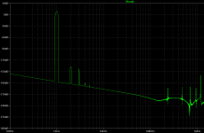
As is out of the box, but with a lower input signal and the added directives to get the fourier analysis done for thd measurements, I find it had rather high thd, well over 0.5% so far. I find this odd.
I've been experimenting myself with a different DOA, mostly based on bryston's, with some changes, which gives far better thd results, although since I'm not planning it for a full swing usage, so I limit the drive to get only 2Vrms output.
I do drive it with a balanced signal, which may not be much different thd wise.
And I get thd at less than 1ppm at 20khz on that one (with 33V rails).
I know there are some differences with this 990 DOA, but still, shouldn't it perform somewhat better than this?
I am using the MJE182/172 on that other DOA, but I don't need a high bias to get good thd results, so the xover distortion can't be bad, even with a low bias. I have it biased at less than 4mA in the vas (symetric topo), and then a bit less than 3.5mA in the outputs (the MJEs).
Maybe it's the models you included in this sim that cause the disappointing results.
I'd be curious to see how well it can be made to perform.
One thing I don't agree with on that 990, is the use of those coils. Although they swear by them to the point of patenting, I'm not seeing the real plus side.
I was looking through this thread and tried out that sim as posted in the rar archive.
As is out of the box, but with a lower input signal and the added directives to get the fourier analysis done for thd measurements, I find it had rather high thd, well over 0.5% so far. I find this odd.
I've been experimenting myself with a different DOA, mostly based on bryston's, with some changes, which gives far better thd results, although since I'm not planning it for a full swing usage, so I limit the drive to get only 2Vrms output.
I do drive it with a balanced signal, which may not be much different thd wise.
And I get thd at less than 1ppm at 20khz on that one (with 33V rails).
I know there are some differences with this 990 DOA, but still, shouldn't it perform somewhat better than this?
I am using the MJE182/172 on that other DOA, but I don't need a high bias to get good thd results, so the xover distortion can't be bad, even with a low bias. I have it biased at less than 4mA in the vas (symetric topo), and then a bit less than 3.5mA in the outputs (the MJEs).
Maybe it's the models you included in this sim that cause the disappointing results.
I'd be curious to see how well it can be made to perform.
One thing I don't agree with on that 990, is the use of those coils. Although they swear by them to the point of patenting, I'm not seeing the real plus side.
me too.I find it had rather high thd, well over 0.5% so far. I find this odd.
Post your .asc file for others to look at it.
me too.
Post your .asc file for others to look at it.
It's not my own, it's the one from post #5.
I reduced the input level to 0.1V and added the .four to get thd reading. Nothing else. It comes with the models, so I just ran it as is. It didn't ask for missing models or anything, so everything must be there.
It should perform better than this, or it's not worth anything.
Did you read the thread? In post #12 I said that the models are DEFECTIVE.
What I said early on was that it was a simulation that runs, that's about it, I don't
have any faith in SPICE with broken models.
In post #20 I give instructions to replace the broken models with Bob C's models, still I do
not have blind faith in simulation.
You seem to have blind faith even with broken models.
The 990 is good, read the AES article, look up John Hardy's work and there are
measurements out there.
The inductors do have a specific purpose, read the AES article and you might learn
what that exactly is.
I fixed up the simulation with Bob C's Bd139/140 for outputs and added simulator
commands for distortion analysis. Output bias and operating points look fine now.
Download the old .zip file and extract it to a folder then add the attached file to that
folder so that you have all the old model files if interested in trying this.
Change the .param Freq= to the desired simulation frequency
Change the .param Amp= (1.414*3)/23 to desired RMS output amplitude in place of 3.
All other parameters for the distortion analysis are calculated in the model - easy to use.
Here is 1 kHz, 600 ohm load, 3 Vrms output, here is the harmonic and THD1 = 0.000006%
(60 ppb) data:
Fourier components of V(vout)
DC component:0.00357529
Harmonic Frequency Fourier Normalized Phase Normalized
Number [Hz] Component Component [degree] Phase [deg]
1 1.000e+03 4.242e+00 1.000e+00 -0.14° 0.00°
2 2.000e+03 2.241e-07 5.283e-08 -166.13° -165.99°
3 3.000e+03 1.126e-07 2.653e-08 53.55° 53.69°
4 4.000e+03 1.208e-09 2.848e-10 158.40° 158.54°
5 5.000e+03 5.602e-10 1.321e-10 -102.52° -102.38°
6 6.000e+03 1.792e-10 4.224e-11 -3.31° -3.17°
7 7.000e+03 3.056e-10 7.205e-11 -1.71° -1.57°
8 8.000e+03 4.276e-10 1.008e-10 -1.84° -1.70°
9 9.000e+03 5.414e-10 1.276e-10 -1.74° -1.60°
10 1.000e+04 6.496e-10 1.532e-10 -1.72° -1.58°
Total Harmonic Distortion: 0.000006%(0.000000%)
Attachments
Last edited:
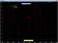
When I simulate the JE990 at unity gain, I get classical "phase inversion" instead of clipping. See attached LTSPICE results. It's fun to dig in to the simulation and figure out exactly how and why phase inversion occurs. Once you understand it, you can eliminate it.
The phase reversal story
Patent
tutorial
Why does it occur op amp output phase-reversal phenomenon?
Neil's list of bad actors
_
The phase reversal story
Patent
tutorial
Why does it occur op amp output phase-reversal phenomenon?
Neil's list of bad actors
_
Attachments
The inductors do have a specific purpose, read the AES article and you might learn
what that exactly is.
I might suggest if one has no idea what the inductors do getting a sim to work is the least of your problems. This topology has been around since 1966 i.e. no sims.
I might suggest if one has no idea what the inductors do getting a sim to work is the least of your problems. This topology has been around since 1966 i.e. no sims.
Scott, I know why the inductors are there.
The AES article mentions circuit analysis using an old HP program, don't remember the
name, and am too lazy to look it up again. They tuned the HF compensation with it.
Oh, I see you are referring to the earlier DOA that they based the 990 on, yes I mentioned
the prior art regarding the inductors in a previous post.
Mark - I'm sure you know that the 990 was intended for use mainly in mic preamps,
so I doubt that it would be used at unity gain. Not sure if it was spec'd for it and am
too lazy to look it up.
I observed it in the lab in 1980 in the old LF OP amps, had a professor who wanted us
to know about it.
Thanks, for the educational input.
so I doubt that it would be used at unity gain. Not sure if it was spec'd for it and am
too lazy to look it up.
I observed it in the lab in 1980 in the old LF OP amps, had a professor who wanted us
to know about it.
Thanks, for the educational input.
Mark,
Thx for the links.
I see the list of opamps experiencing this CM range phase reversal is rather short.
I wonder if our favourites like NE5534, AD797 exhibit this phase reversal too?
I assume that AD797 does, since it is included in MT-036 note.
So I guess a question to Scott is, was there no way to remedy this in the AD797 design ? I could think of a few possible reasons, might be lame thinking.
1) maybe it is just the nature of the topology and it is best done externally with diodes
2) AD797 is not intended to be used as a voltage follower
3) extra cost, complexity
4) would affect its perfromance
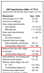
The 990 datasheet permits unity gain operation and includes several GBW and risetime numbers specifically measured at unity gain. It avoids phase reversal by forbidding you to drive the input higher than (toprail - 4.5V) or lower than (bottomrail + 4.5V).
Doctor it hurts when I do this? Don't do that.
Doctor it hurts when I do this? Don't do that.
Attachments
Confirmed, good job Pete. Do you have any thoughts of actually building one of these?
I always admired the analysis done in the AES article from the time back in college
when I first read it. The LM394 is really optimized for lowZ sources so it would not
be optimal for a MM phono pre, better for MC but the LM394 is outdated as compared
to some of the newer/better devices. Sure I could build it with newer devices or JFETs
in place of the them. People on the net have built JFET versions.
It is really fairly close to a Self configuration, this came first of course.
Another thing that I like is that the output stage is class A for reasonable loads and
Class A makes sense in a preamp where less than 1W of output stage power is not
a significant penalty.
I have most of the parts and might build it for kicks some rainy day.
I've had it on my mind to build/mod a preamp so that I can A/B preamp modules from
a remote. The modules might be in something like the JC2 form factor. The 990 might
make a neat vintage benchmark.
The 990 datasheet permits unity gain operation and includes several GBW and risetime numbers specifically measured at unity gain. It avoids phase reversal by forbidding you to drive the input higher than (toprail - 4.5V) or lower than (bottomrail + 4.5V).
Doctor it hurts when I do this? Don't do that.
Ah, okay good point, thanks for looking it up.
I'll just point out that with the 990 on +/- 24V rails, the input limit is +/- 19.5V, not too bad.
But yes I agree, better to have a circuit that never does it.
Last edited:
- Home
- Amplifiers
- Solid State
- Simulation of the JE-990 OP Amp By Deane Jensen