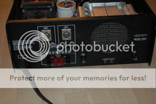
I recently got a pretty old Hafler P500 power amp on ebay -which should be almost identically with the more know DH-500 model. I want bring it into action for my home recording studio monitoring.
As the seller confided, the amp made a three days test run (but without a full output power rehearsal) without any flaws. I opened the housing but have the amp not powered up yet.
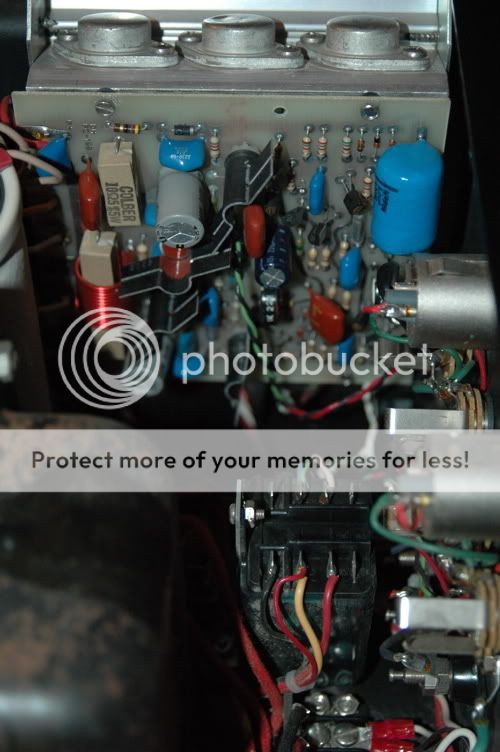
The mosfets seems to be the original ones (3x 2SK176, 3x SJ76 with Hafler part numbers, Grade 2). There is a dent on one of them (right array, the one in the middle -as shown on the pictures). I assume its not blown but rather physically hit/squished by something. The dent goes to the inside of the housing. -It would be nice if anyone has an opinion here.
I would like to know now if my amp is technically healthy and well adjusted at all. So, it would be great if could get your helpful hints and answers to my questionnaire:
- Step by step. What to do first?
- What to know/What to test? (what are the important parameters
output power, transistor bias, equal channel loudness, DC on
speaker outputs ??)
- How/Which way of test proceeding?
- Which specific value-ranges are healthy, which are not?
- How to do the adjustment, if necessary (I have noticed the
trim-pots on the boards)
- mandatory maintenance (changing electrolytic capacitors et cetera)
”Qualifications”: I am a musician in the first place but semi-experienced in building tube gear (made some guit-(pre)amps, a tube eq, psu’s for vintage modules). Apart from screwdrivers and black coffee I have a two channels oscilloscope, audio generator and a VTVM on my bench.
Big thanks in advance for any advice
Toby

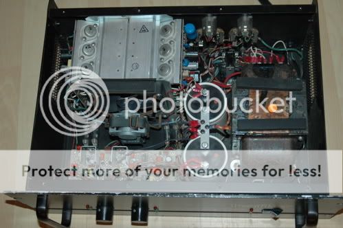


As the seller confided, the amp made a three days test run (but without a full output power rehearsal) without any flaws. I opened the housing but have the amp not powered up yet.
The mosfets seems to be the original ones (3x 2SK176, 3x SJ76 with Hafler part numbers, Grade 2). There is a dent on one of them (right array, the one in the middle -as shown on the pictures). I assume its not blown but rather physically hit/squished by something. The dent goes to the inside of the housing. -It would be nice if anyone has an opinion here.
I would like to know now if my amp is technically healthy and well adjusted at all. So, it would be great if could get your helpful hints and answers to my questionnaire:
- Step by step. What to do first?
- What to know/What to test? (what are the important parameters
output power, transistor bias, equal channel loudness, DC on
speaker outputs ??)
- How/Which way of test proceeding?
- Which specific value-ranges are healthy, which are not?
- How to do the adjustment, if necessary (I have noticed the
trim-pots on the boards)
- mandatory maintenance (changing electrolytic capacitors et cetera)
”Qualifications”: I am a musician in the first place but semi-experienced in building tube gear (made some guit-(pre)amps, a tube eq, psu’s for vintage modules). Apart from screwdrivers and black coffee I have a two channels oscilloscope, audio generator and a VTVM on my bench.
Big thanks in advance for any advice
Toby
Yes, and I have the dh-500 schematic.
What I have picked up here to date:
Bias current should be 350 - 400ma (measured through the fuses)
The 500er boards should be equal to the pcb’s from the dh-220 with trim-pots for:
P1 offset adjustment
P2 bias adjustment
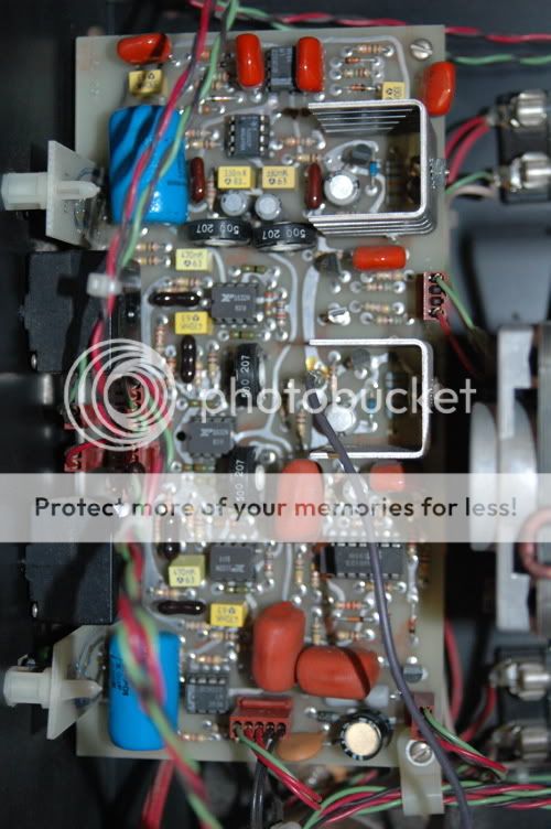
I guess the two trim-pots on the front site board allow fine tune the stepped volume-pots
What I have picked up here to date:
Bias current should be 350 - 400ma (measured through the fuses)
The 500er boards should be equal to the pcb’s from the dh-220 with trim-pots for:
P1 offset adjustment
P2 bias adjustment
I guess the two trim-pots on the front site board allow fine tune the stepped volume-pots
Make up a shorting plug that connects the input to ground. Plug it into one channel, and with your DVM connected to the speaker outputs and set on DC, check the voltage. Adjust so that is as low as possible, but anywhere under 30mV or so will be fine. Plug in a cheap speaker and a source signal, and run for half an hour or so at normal listening level to get the amp warmed up. Check voltage again, and adjust as required.
Repeat for other channel, put the lid back on, and enjoy.")
Repeat for other channel, put the lid back on, and enjoy.
toby_somerset said:Somebody knows what function the four trim-pots on the front board serves?
Impossible to say without a schematic. However, if the amp is now working, I'd leave them well alone unless you find out exactly their purpose. Tweaking them just to see what they do is likely to end in tears!
- Status
- This old topic is closed. If you want to reopen this topic, contact a moderator using the "Report Post" button.
- Home
- Amplifiers
- Solid State
- Need checklist advice for health check-up - Hafler P500 (DH-500) Power Amp