For a long time I have been fascinated with the "circlotron" output stage topology because you can use N-channel devices exclusively and it is totally balanced, unlike quasi complementary symmetry. The downside though is you have to have two floating dc supplies for every output stage. Imagine a 5.1 HT setup! Anyway, a while back I saw this setup in Glass Audio and have been bursting to give it a try. The big advantage is that you can use a single supply for all stages just like in other amp topologies. I did make a small one a while back but wound up a small ferrite transformer and because of the lack of inductance the LF response was not that great, but it did work... So, on the weekend I got busy and pulled apart and rewound an old 120va tranny with 43 turns quadfilar of 1.25 mm wire. I just used what I had and what would fit. Another really good thing is that the transformer doesn't have to have any great audio qualities, it's major job is to transfer dc to the two electrolytic caps that are going oppositely up and down at an audio rate. The tranny is sort of like a double ended see-sawing (teeter-tottering for you Septic Tanks
 ") ) common mode choke. You can make it out of any old junk, just so long as the windings are identical voltage. at the moment I am shooting for 200w into 8 ohms down to 50Hz with a *single* 40v rail. Will post further pics as the project proceeds.
) common mode choke. You can make it out of any old junk, just so long as the windings are identical voltage. at the moment I am shooting for 200w into 8 ohms down to 50Hz with a *single* 40v rail. Will post further pics as the project proceeds.
BTW, I refer to it as a Tetrahedron topology because you can redraw it as a perfect 3D tetrahedron with one tranny winding as the top edge and the other tranny winding as the bottom edge. CT's to power and ground. Each end of the bottom edge has a fet source and a cap negative on it. They split to opposite ends of the top edge so each end of the top edge has a drain and a cap positive. Draw it on paper. Looks cool. Great to dream about.
Anyway, a while back I saw this setup in Glass Audio and have been bursting to give it a try. The big advantage is that you can use a single supply for all stages just like in other amp topologies. I did make a small one a while back but wound up a small ferrite transformer and because of the lack of inductance the LF response was not that great, but it did work... So, on the weekend I got busy and pulled apart and rewound an old 120va tranny with 43 turns quadfilar of 1.25 mm wire. I just used what I had and what would fit. Another really good thing is that the transformer doesn't have to have any great audio qualities, it's major job is to transfer dc to the two electrolytic caps that are going oppositely up and down at an audio rate. The tranny is sort of like a double ended see-sawing (teeter-tottering for you Septic Tanks ) common mode choke. You can make it out of any old junk, just so long as the windings are identical voltage. at the moment I am shooting for 200w into 8 ohms down to 50Hz with a *single* 40v rail. Will post further pics as the project proceeds.BTW, I refer to it as a Tetrahedron topology because you can redraw it as a perfect 3D tetrahedron with one tranny winding as the top edge and the other tranny winding as the bottom edge. CT's to power and ground. Each end of the bottom edge has a fet source and a cap negative on it. They split to opposite ends of the top edge so each end of the top edge has a drain and a cap positive. Draw it on paper. Looks cool. Great to dream about.
Attachments
There still must be something in that Melbourne water....
Graham, good work - any running examples yet ?.
Are these for your new subs ?.
You mentioned that you wife does not like thunder - yesterday morning it frightened the living beejeezus out of me and my lady too.
......Sunday morning sleeping in soundly after a nice evening was rudely interrupted by a lighning strike, I swear directly over the top of her roof at precisely 6.21 AM.
As a reflex action both of us instantly flew out of bed and then looked at each other, still half asleep but wide awake at the same time.
You need a bit more than 200W to go near to that.
Eric / - nothing can surprise me after that awakening.
very interesting, you might also want to look at...
my little project
http://www.diyaudio.com/forums/showthread.php?s=&threadid=8725&highlight=inductance
skip all the way to the bottom of the page for an accurate schematic..
I've built the circuit but have not connected the transformers yet.
I'm currently having problems with heat conduction as the transistors don't seem to couple well to the heatsink no matter what I do.
Actually, there seems not to be any coupling at all... so it's shelved for the moment. I'm using silicone pads and I think I will replace them with sth else.
I'm very interested to see how much bass you'll manage to get by winding your own toroid as this what I envisage to do myself eventually. One thing I want to know is this : do power toroids have ferrite cores ? or are they tape wound ? or iron-powder ? Is there a default core for this application ? I don't want to take them apart to find out (yet)..
regards
Stelios
Stelios, thanks for telling me about 'your little project', I'm printing a hard copy of it right now so I can have a closer squiz at it. AFAIK mains frequency toroids would all have strip wound iron/steel cores because this is the only stuff that will make enough inductance with a reasonable amount of turns for use at low frequencies.
I actually used an EI type transformer because that was what was available, and it is relatively easy to wind, although that few turns on a toroid doesn't present too much of a problem. I would have liked to use one if I had one. Yesterday I ran it up on 50Hz ac on the bench and observed the magnetising current versus voltage and decided that at 50Hz one complete centre tapped winding of 43 + 43 turns is good for about 25Vrms. Proportionally higher at higher frequencies and vice versa. 25v = 78 watts into 8 ohms, double that into 4 ohms, and would need close to 40vdc supply rail. Hopefully I'll get something going by the end of the week.
BAM, the gates are indeed driven in antiphase and biased with respect to earth. The circuit has a voltage gain of 2.
mrfeedback, probably someone at the antipode of your house has a 7 Hz Tesla coil cranked up and focussed on you.
Q
I have to say that I find this type of circuits really perplexing.
Any links where I can find out more about its operation ?
I can't understand the purpose of the capacitors...
Circlotron:
I have also written a small spice code for R. Burfoot's circuit but unfortunately I can't get it to work. You're welcome to it though if you want. (I use Winspice).
regards
stelio
There is a patent covering the tube version dating back to the forties or something. I'll have to look for it again.
Who is R. Burfoot, the original designer?
Stelios, think of it like this (works for me anyway). Two see-saws one above the other. A reasonable space between the two. The upper see-saw with the pivot point going to + volts. The lower see-saw with the pivot point going to earth. Left fet reaches from left end of lower ss to left end of upper ss. Right fet reaches from right end of lower ss to right end of upper ss. Cap1 from bottom left to top right, and cap2 from bottom right to top left so they cross like an "X". Fets pull see-saws so they alternately touch together at left end, or touch together at right end. Touching actually means clipping. Caps are like struts that lock the motion of the see-saws together so they always move accurately in unison. It parallels the operation of the transformer and makes it behave as though it had zero leakage inductance between it's 4 windings. All 4 windings are always driven, unlike a conventional class AB cct where for a lot of the cycle only one half of the primary winding gets driven, making for poorer prim to sec coupling and inefficient use of the copper. Actually this feature is only an issue if you had the speaker driven off a secondary winding like in a high impedance tube cct; for this one you can run the speaker from a source to source connection. I think the ultimate in aesthetic symmetry would be to use a dual voice coil loudspeaker and drive one coil from the sources and the other from the drains. Another thing, seeing each drain looks into the other source, we have a current sink hooked onto a voltage source. Very happy arrangement. Niceness definitely radiates out of this circuit.
Who is R. Burfoot, the original designer?
Stelios, think of it like this (works for me anyway). Two see-saws one above the other. A reasonable space between the two. The upper see-saw with the pivot point going to + volts. The lower see-saw with the pivot point going to earth. Left fet reaches from left end of lower ss to left end of upper ss. Right fet reaches from right end of lower ss to right end of upper ss. Cap1 from bottom left to top right, and cap2 from bottom right to top left so they cross like an "X". Fets pull see-saws so they alternately touch together at left end, or touch together at right end. Touching actually means clipping. Caps are like struts that lock the motion of the see-saws together so they always move accurately in unison. It parallels the operation of the transformer and makes it behave as though it had zero leakage inductance between it's 4 windings. All 4 windings are always driven, unlike a conventional class AB cct where for a lot of the cycle only one half of the primary winding gets driven, making for poorer prim to sec coupling and inefficient use of the copper. Actually this feature is only an issue if you had the speaker driven off a secondary winding like in a high impedance tube cct; for this one you can run the speaker from a source to source connection. I think the ultimate in aesthetic symmetry would be to use a dual voice coil loudspeaker and drive one coil from the sources and the other from the drains.
Another thing, seeing each drain looks into the other source, we have a current sink hooked onto a voltage source. Very happy arrangement. Niceness definitely radiates out of this circuit. ta
Hi Circlotron,
thanks for the explanation
I'll have to print it out and give some more thought later.
I can't say I really like the idea of the capacitors but if they're needed for the circuit to work, so be it.
Another idea perhaps would be to drive two different units, one from the sources and one from the drains, but I don't know how well that would work.
R. Burfoot is the original designer, yes. I have some more info on my first two postings in that thread. I also have the original article too if you're interested.
regards
Stelios
de-vine images
After consuming half a bottle of red wine I find myself drawing see-saws all over a piece of printer paper.
I think I understand your description, but I have a question. What is the point of having the opposing SS arrangement? I mean, what is the benefit of having the upper SS move at all? And furthermore, would it not be more beneficial to have the upper SS move synchronously with the lower SS, thus producing a constant Vds across the FETs rather than a swinging Vds in the current arrangement, where at one end the SS touch while at the other they are widely separated?
I'll finish the rest of the bottle while you and I consider whether my question makes any sense whatsoever.
BAM
No Sir! If I was suggesting that this cct needed burning in or suchlike then I wouldn't be so sure of myself.traderbam said:"Niceness definitely radiates out of this circuit. "
You have definitely LOST THE PLOT, mate!
Radiating niceness? Tube amp builders would understand this concept I'm sure, both in a schematic and in hardware. It's related to the figurativeness of aesthetics. Sort of hard to quantify but real enough nonetheless. I just express it in a tongue-in-cheek sort of way.de-vine images. uhhh... spare me....
Constant Vds across the fets? I hope your head is feeling better this morning. 
The opposing SS arangement allows you to use only one supply rail to power the two floating capacitor "supplies". You could just have a pair of source followers feeding each end of the bottom seesaw only, with the drains going straight to V+. Trouble is, then when one source is pulling up it depends entirely on the transformer to pull the opposite end of the load down. Lousy cheap tranny = crook results. But with a top seesaw as well, a cap from the drain of the same fet pushes that end of the load down while the same fet's source pulls the other end of the load up. But this drain doesn't push the opposite side source down in an uncontrolled manner even though the drain is a current sink with a fairly high compliance because the source is a voltage source and it is the boss over the current sink. What's more, if the left source goes up, it pushs the right drain up both by capacitor coupling and transformer coupling. This then sort of pushes the left drain down. Everything co-operates together by being locked to everything else.traderbam said:What is the point of having the opposing SS arrangement? I mean, what is the benefit of having the upper SS move at all? And furthermore, would it not be more beneficial to have the upper SS move synchronously with the lower SS, thus producing a constant Vds across the FETs rather than a swinging Vds in the current arrangement, where at one end the SS touch while at the other they are widely separated? BAM
Constant Vds across the fets?
I hope your head is feeling better this morning. ...go right to the source and ask the horse....
OK. I finally found it. The original patent is US 2,648,727. http://patimg1.uspto.gov/.piw?docid...=2648727.WKU.%26OS=PN/2648727%26RS=PN/2648727
Various variations on a theme, the most relevant one in the picture here. Output is taken from the anodes, but fundamentally no different.
OK. I finally found it. The original patent is US 2,648,727. http://patimg1.uspto.gov/.piw?docid...=2648727.WKU.%26OS=PN/2648727%26RS=PN/2648727
Various variations on a theme, the most relevant one in the picture here. Output is taken from the anodes, but fundamentally no different.
Attachments
Hardware, not vapourware.
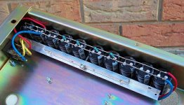
Righto then. I got really busy during the week and threw a test bed together. I used a pair of IRF540 fets 100v 28 amps 150w IIRC because I had a few. The DC rail measured 41.7 volts from a 29 VAC 7 amp winding on the tranny. The amazing part was I actually used a chassis rather than just making a rats nest all over the bench like in previous times. At least this way it is portable. The chassis is actually part of a 19 inch rack mount thing with the mounting flanges turned inward. When it was finished I didn't do much else other than put in a low level signal and connect a loudspeaker and check that it actually worked. It did. I didn't pull more than perhaps a quarter of a watt out of it because of the very low signal level I fed it. As it stands it should do 100 watts into 8 ohms. It will have to wait for another day for further tests.
Righto then. I got really busy during the week and threw a test bed together. I used a pair of IRF540 fets 100v 28 amps 150w IIRC because I had a few. The DC rail measured 41.7 volts from a 29 VAC 7 amp winding on the tranny. The amazing part was I actually used a chassis rather than just making a rats nest all over the bench like in previous times. At least this way it is portable. The chassis is actually part of a 19 inch rack mount thing with the mounting flanges turned inward. When it was finished I didn't do much else other than put in a low level signal and connect a loudspeaker and check that it actually worked. It did. I didn't pull more than perhaps a quarter of a watt out of it because of the very low signal level I fed it. As it stands it should do 100 watts into 8 ohms. It will have to wait for another day for further tests.
Attachments
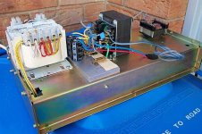
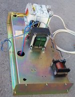
Another view. Note the tranny with the green wire. I stripped and rewound it as per the details in the 4th post. The other little tranny is the phase splitter, hexfilar wound 525 turns on a 3C85 or N87 ferrite ETD49 size core. ferrite core no less. Works extremely well.
Attachments
Hi Circlotron
Good, good... Just as I was going to ask for a few more pics...
How did you wind the output trafo ? I can't really tell from any of the posts - did you mean your 4th post ? I still couldn't make it out.
Did it take a long time ?
What are the galvanised steel bits on that grey thing with the capacitors on it ? how can one obtain them ?
I will be looking forward to the final results
Stelios
Is 11pm here. Feeling too tired and lazy to describe how to wind tranny right now. Yes, the 4th post in the thread. That grey thing is a slab of aluminium 10mm thick and the things on it are screw-on clips to hold TO-220 and TO-247 devices without using the mounting hole. Allows for extra creepage distance in high voltage applications. These pieces were pulled out of the bin at work and the clips get made special for us so sorry.
I have a 5kva transformer with 4 x 240v windings and there is a little voice inside my head that keeps whispering ....output transformer....output transformer.....
Yes, the 4th post in the thread. That grey thing is a slab of aluminium 10mm thick and the things on it are screw-on clips to hold TO-220 and TO-247 devices without using the mounting hole. Allows for extra creepage distance in high voltage applications. These pieces were pulled out of the bin at work and the clips get made special for us so sorry. I have a 5kva transformer with 4 x 240v windings and there is a little voice inside my head that keeps whispering ....output transformer....output transformer.....
- Status
- This old topic is closed. If you want to reopen this topic, contact a moderator using the "Report Post" button.
- Home
- Amplifiers
- Solid State
- Tetrahedron output stage topology.