I posted in the subwoofer forum looking for some help in trying to modify a subwofer amp (remove high pass ruble filter) and am not getting much input. I thought that maybe you folks here might want to give it a stab.
Please see my sub amp post.
I would appreciate any help you could give.
mike
Please see my sub amp post.
I would appreciate any help you could give.
mike
Thanks Anatech. I will try to get a better drawing done this week some time. I was having a hard time tracing this out and put up the diagram in hopes that the general topology might look familiar enough to someone that they could guide me a little further on what to focus on.
That said I will try to get the values and reconfirm the connections as best I can. Some stuff is hard t see being under the closed part of the "chasssis".
mike
That said I will try to get the values and reconfirm the connections as best I can. Some stuff is hard t see being under the closed part of the "chasssis".
mike
That schematic doesn't look right.
Here is the generic Kiega subwoofer crossover, found in 85% of most plate amps. Other brands will be more similar than different.
http://www.apexjr.com/images/sr3.jpg
R26 and R27 control the frequency and Q of the boost/filter circuit (in conjunction with C14, C15).
If you want it flat to 20Hz with a Q=1, I suggest 39.8K and 159.2K (for 0.1F). 39K and 150K are probably close enough, I doubt the caps are better than 5%.
Thanks djk, I thought it looked pretty strange too. I will print out your schematic, grab the amp and spend some quality time with a magnifying glass. ") I peeled off the moose snot and opened up the covered part so that will make it a lot easier to see what is going on. It is not so easy for 46 year old eyes to trace those little lines accurately so mistakes are quite possible.
I peeled off the moose snot and opened up the covered part so that will make it a lot easier to see what is going on. It is not so easy for 46 year old eyes to trace those little lines accurately so mistakes are quite possible. 
I am sure we will figure it out eventually. Your help is much appreciated.
mike
I peeled off the moose snot and opened up the covered part so that will make it a lot easier to see what is going on. It is not so easy for 46 year old eyes to trace those little lines accurately so mistakes are quite possible. I am sure we will figure it out eventually. Your help is much appreciated.
mike
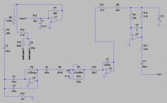
I finally got some time to look at it more carefully and improve the drawing. I did find some errors. The new drawing is attached below. It looks like the LP is in the circuitry between U4 and U2 but that input to U4 just has me baffled. I have check over and over again and C3 and C4 are connected together at the end away from the op amp and on the other end one is connected to the output and the other is connected to the inverting input. It has to be some king of feedback scheme but I have no idea what it is doing and how we get any output from it.
It seems like the only capacitors even remotely capable of providing a high pass function are 2, 3, 4, 5, and 11. Of course it is entirely possible that the HP is implemented in the circuitry surrounding the power amp module which I have not traced.
Unless anyone has any insight I guess my next step is to put it back together and drive it with a signal and measure with my DMM to see where a sub 40Hz signal begins to be attenuated. Sure wish I had a scope.
puzzled in Indiana
mike
Attachments
- Status
- This old topic is closed. If you want to reopen this topic, contact a moderator using the "Report Post" button.
- Home
- Amplifiers
- Solid State
- Help with mdification of subwoofer amp