Hi guys,
Four years ago I have made myself an amplifier using a schematic from 1986 (at least in the book I found). I have posted it here that time but only to ask if it might work, and it did after having changed all the transistors to newer models. Anyway I made a mess of a wiring, used an old pcb from another amplifier and very old capacitors for rectification. I sounds pretty good but makes a bit of noise. I decided to rebuild it. I am currently using it for a subwoofer because it reproduces the bass really good and the noise doesn't seem to be noticeable. BUT being such an old schematic, and having that troubeling noise, I was wondering if there is any way I can improve it. I have to say that I have some electronic knowledge but I am no specialist so if you have the time to give me some advice please do so. I have no characteristics of the amplifier I only know that it has a gain of about 59 dB but I have momentarily no equipment for testing it.
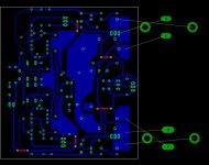
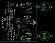
So my plan is to first improve the schematic (if possible) than create the proper pcb an I hope by that time to have a signal generator and an oscilloscope and see if my work was worth or not.
Here is the schematic
Four years ago I have made myself an amplifier using a schematic from 1986 (at least in the book I found). I have posted it here that time but only to ask if it might work, and it did after having changed all the transistors to newer models. Anyway I made a mess of a wiring, used an old pcb from another amplifier and very old capacitors for rectification. I sounds pretty good but makes a bit of noise. I decided to rebuild it. I am currently using it for a subwoofer because it reproduces the bass really good and the noise doesn't seem to be noticeable. BUT being such an old schematic, and having that troubeling noise, I was wondering if there is any way I can improve it. I have to say that I have some electronic knowledge but I am no specialist so if you have the time to give me some advice please do so. I have no characteristics of the amplifier I only know that it has a gain of about 59 dB but I have momentarily no equipment for testing it.
So my plan is to first improve the schematic (if possible) than create the proper pcb an I hope by that time to have a signal generator and an oscilloscope and see if my work was worth or not.
Here is the schematic
Attachments
first of all, i'd increase C2,3 to 470uf each to improve bass response. i'd also increase C8 to 1uf and reduce R31 to about 200-300 ohms to improve turn-off of the drivers. same for the bias circuit, increase C4 to 1uf or more, reduce the values of R24,25 by about 90% (1k for R24, 200 for R25).
reduce R1 to about 10k, increase R4 to 100k. your input impedance is determined by R4 mostly, since the input impedance of a diff amp is near infinity. add "flyback" diodes across the C-E terminals of the output devices to protect the devices from reverse voltage spikes.
also, you might check and see (with an oscilloscope) if this amp is oscillating, since there are no miller caps in this amp. that might be where your noise is coming from.
Hi Red,
The base of Q13 is connected to the emitter of Q11, right? You show it shorted to the supply. R24 in your bias circuit is in a position where if it fails, your output stage will go high bias and burn out possibly. The variable element should be in the emitter-base leg wit ha resistor to define the maximum bias limit (so you can't short the base to the emitter of Q8)
You could replace C2,3 with one non-polar 220 ~470 uF, bypassed with a film cap (you could probably use a polarized electrolytic here as this voltage will be very low). C8 should be increased to 1 ~ 10 uF (as unclejed613 suggested), bypass again or use a film cap. R31 is normally around 220 ohms, just on average. No need to waste power here. R32, 33 should be non-inductive types, as should R34.
I see you are using R1 and R4 as a pad. That's okay, although BJT differential pairs sound better driven with a low impedance source. Your call and it's a "tweak" after you have the basic circuit running. In that case you would install your pad at the input of the amp before the buffer, R1 should then be decreased to 100 ohms and R4 may not be required. I would use a DC blocking cap on the input if I were you.
Unclejed613's suggestion of flyback diodes is always a good idea. 1N5402 should be okay, 1N5404 would be better (just voltage breakdown).
Also, as Unclejed613 stated, you should always check the circuit with an oscilloscope to make sure it isn't oscillating. Also check the frequency response for peaks that would encourage it to "ring". This normally occurs somewhere from 50 KHz to 1 MHz depending on many things.
-Chris
Thank you for your prompt answers.
The first thing i have to mention is the fact that I have connected Q13 wrong in the schematics. It is connected to the emitter of Q11 and not to the rails.
I was thinking to change C2 and C3 with a single non-polarised capacitor and I will increase it. I will also change R1 and R4. I will try both your advices and see which one works better. Also I will add a capacitor on the input I was thinking at a 1uF but I don't know if that is large enough.
I was thinking to change somehow the output transistors because I want to be able to use it on 4 Ohms load also.
that's always a good idea..... make one change at a time and test it. same thing applies to config files in software. if you make a bunch of changes at once and it crashes, it;s much harder to find out what caused the crash. i occasionally get equipment that has been "modded". usually has something ugly it's doing to the sound as a result of the modifications, but since several mods were applied simultaneously, it's sometimes difficult to find out exactly which one caused the equipment to go south......
That's when charges go higher ....
Hi unclejed613,
This may make the repair job too expensive to proceed, but that is better than a technician losing hours upon hours of work for nothing.
Time to withdraw and find a battle you can win.
-Chris
Hi unclejed613,
At this point you would ignore the mods that do not impact the operation, but check the solder joints. The customer is then charged to return the unit to a stock condition leaving the non-harmful mods.but since several mods were applied simultaneously, it's sometimes difficult to find out exactly which one caused the equipment to go south
This may make the repair job too expensive to proceed, but that is better than a technician losing hours upon hours of work for nothing.
Time to withdraw and find a battle you can win.
-Chris
Red,
some good suggestions here. You should defineltry check the output once running to make sure there is no oscillation. If you are hearing shh sound out of the speaker, the amp probably is.
Make the changes suggested, and the check for oscillation. If you have this problem, let us know and we can make some proposals to tame it.
red, to be on the safe side, I would include place on the board for
1. 2 comp caps from each collector to base of Q9 and Q7 (your VAS transistors). You can compensate this amp a number of ways, but this is probably the safest and bes t understood. Value if needed (I think you will need them) will be in range of tens of pF (e.g. typical value is 33pF). Use good quality caps here and not ceramic.
2. Put place on the board for a resistor and cap (again just a few pF connected between the collector of Q7 and the junction of R21 and R22
Hi,
is the bias adjustment pot still on the base to collector side of q8?
If so then swap the transistor to a bd140 (PNP) so that the pot is on the base emitter side.
The gain of the basic amplifier is r22/r21+1=22000/560+1=40.28=+32.1db.
the input attenuator is 22/(22+27)=0.449=-7db.
overall gain =32.1-7=25.1db (not +59db) about 18.1times.
sensitivity for 80W into 8ohms is approximately 1.4Vac This is quite high so volume control usually needs to be turned high up.
Once you have this amp running properly, then changing r1 to 1k0 will be much more suitable. That will give you back some of the missing treble.
Hi unclejed613,
Assume anything on Ebay is not functioning properly or is cosmetically challenged in some way. Hence my term for Ebay, Eeeek bay.
-Chris
Yes. A terrible fault called "Struck by Technician", or another I like "TIM, or Technician Induced Malfunction". Understand the word "technician" is used very loosely here.it seems that ebay is the answer for getting rid of "frankensteined" equipment that doesn't quite work right.
Assume anything on Ebay is not functioning properly or is cosmetically challenged in some way. Hence my term for Ebay, Eeeek bay.
-Chris
AndrewT I haven't change the bias adjustment pot so i will try to change Q8 to a bd140 and give it a shot; also I will change R1 but only after I have it running. thanks ")
Bonsai you are totaly right and I will make the ajustmenst to the board for those capacitors. thanks
anatech , unclejed613 I have no ideea of what you are talking about... perhaps you are right about ebay but personaly I don't use it in any way. I prefer to build my stuff, if not posibble I seek to buy only things that I have personaly tested.
Thanks a lot for the replys and I'll continue the work to see what comes of it.
watch the order of the legs.red said:I haven't change the bias adjustment pot so i will try to change Q8 to a bd140 and give it a shot
If the Vbe multiplier were connected with wires back to the PCB this change is easy.
But, you will have to move emitter leg out of the way. Bend it forwards.
Spread the base and collector legs to double the pin pitch gap and insert these two legs into the outer pair of pads. Now wire the bent emitter leg to the empty middle pad. A very short length of 0.6mm tinned wire does this nicely. You may feel happier with some insulation on that link wire to prevent accidents.
I haven't made the new pcb and the old one has the bias circuit as diffrent smaller pcb that it hold in place by Q9 that is screwed to the heat sink of the power transistors...
My belief right now is that the noise is produced by the wiring and the old parts I was using. But I did miss the treble so the old schematic might have it's defects...
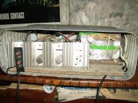
I will post some pics for you to see the mess I have made in that amp when I had no ideea how to wire an amp...(not that now I'm much better but still... )
My belief right now is that the noise is produced by the wiring and the old parts I was using. But I did miss the treble so the old schematic might have it's defects...
I will post some pics for you to see the mess I have made in that amp when I had no ideea how to wire an amp...(not that now I'm much better but still...
)
- Status
- This old topic is closed. If you want to reopen this topic, contact a moderator using the "Report Post" button.
- Home
- Amplifiers
- Solid State
- Help Modifying an amplifier schematic