Hi Roger,
thanks for clearing that one up! So in fact you would like a schematic")
A parts list is to my understanding just a list connecting names with parts, like Q1=BC550C and so on.
Have fun, Hannes
PS: congrats that you read colour codes like a book! I didn't bother with that and use now only Dale resistors that have their value written upon them
thanks for clearing that one up! So in fact you would like a schematic
A parts list is to my understanding just a list connecting names with parts, like Q1=BC550C and so on.
Have fun, Hannes
PS: congrats that you read colour codes like a book! I didn't bother with that and use now only Dale resistors that have their value written upon them
LK1 Re-cap!
Everyone,
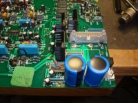
I had to guess a bit about the size of a cooked R61 resistor, but it was no mystery to change ALL of the elctrolytic capacitors. I made this decision because of the two swollen caps, plus the loud rushiong noise from the MC channel. This involved replacing all 6 of the 322mf, 50v capacitors and it made it quiet. With the high failure rate, I decided to cahnge them all. Good move because the 22mf caps measured from300PF to 26MF. Only the 26mf unit was very close to the posted value. Most were less than 10mf! I used vertical mount 10,000mf, 25v capacitors for the main power supply filters. See pix for the location. It works fine now.
Everyone,
I had to guess a bit about the size of a cooked R61 resistor, but it was no mystery to change ALL of the elctrolytic capacitors. I made this decision because of the two swollen caps, plus the loud rushiong noise from the MC channel. This involved replacing all 6 of the 322mf, 50v capacitors and it made it quiet. With the high failure rate, I decided to cahnge them all. Good move because the 22mf caps measured from300PF to 26MF. Only the 26mf unit was very close to the posted value. Most were less than 10mf! I used vertical mount 10,000mf, 25v capacitors for the main power supply filters. See pix for the location. It works fine now.
Attachments
Please note, that it is necessary to mounting the regulator devices ( presently mounted on heatsink) on the bottom of the aluminium envelope (aluminium case) to use this case for the heatsink function. Now the life expectancy of the caps near by the old heatsinks is higher because now don't burn longer. Stuff for electric isolated mounting is additional necessary.
Various compensating caps you must solder directly on the leads of the regulators (LM317 and two BjT's in TO-126/SOT32 outline - as I know). now the length of the additional wiring (at whole 9 leads) are not longer a problem.
Use in all cases 63V versions. 1000uF/63V for the main caps behind the rectifier e. g. is a much more better choice than 4700uF/25V.
High Capacitance values are nonsense in general, if capacitor is connected in front of the voltage regulator instead behind.
Last edited:
Help needed please dead LK2
I have an LK2 that has dropped a channel, I assume that I need to replace some of the caps, I am after a schematic just to get a better understanding if anyone can help please?
As this is an old amp now and I am new to trying to repairing amps any advice to what I should replace whilst I have the unit open would be great.
Regards, Dean.
Here you have the Linn LK1 service manual;
http://www.audio-circuit.dk/Schematics/Linn_LK1_sm.pdf
And here for the Linn LK2;
http://www.audio-circuit.dk/Schematics/Linn_LK2_sm.pdf
Hello,
Here is the schematic for the Lk280 amplifier. I wonder what component upgrade would be worth it. The 6 x 100F capacitors?
Tomorrow I'll write more about my issues with this amp after the PS caps upgrade.
You need to go through a security check before navigating to the file. Simply go first to Audio Circuit Denmark
check out the first PDF link by post #1 aboutIt would seem the link to the schematic no longer works, any help please?
http://www.diyaudio.com/forums/powe...arround-power-supply-linns-preamp-lk-1-a.html
URLs are Death.Here you have the Linn LK1 service manual;
http://www.audio-circuit.dk/Schematics/Linn_LK1_sm.pdf
And here for the Linn LK2;
http://www.audio-circuit.dk/Schematics/Linn_LK2_sm.pdf
here my own schematics:
Attachments
-
C_tmp_Linn LK2, LK2-80_ckt complete.pdf30.2 KB · Views: 720
-
C_tmp_Linn LK2, LK2-80_ckt buffer.pdf10.6 KB · Views: 444
-
C_tmp_Linn LK2, LK2-80_ckt bias.pdf9.7 KB · Views: 448
-
C_tmp_Linn LK2, LK2-80 second stage_ckt.pdf13 KB · Views: 439
-
C_tmp_Linn LK2-80 II Kloud_ckt.pdf71.9 KB · Views: 541
-
C_Linn_Kloud control_ckt.pdf13.9 KB · Views: 404
-
C_Linn Kloud_control_ckt.pdf15.4 KB · Views: 402
-
C_Linn Kloud control_ckt.pdf48.3 KB · Views: 500
-
C ...-Linn LK2-80 Ampmod.ckt.pdf58.8 KB · Views: 617
-
C ...-A-Linn LK2-80 orig.sim.ckt.pdf34.5 KB · Views: 821
continuation
Attachments
Let's go on with tweaking classic LK1 and LK2.
Any ideas how do isolate 1st stage properly? I guess one resistor won't be sufficient.
Could you please explain to help me getting an opinion?
dito

I do not know about tweaks but the LK2-80 has an interesting schematics.
Here some items I can notice:
1) Fully regulated power supply (even the output stage)...but the 1st and 2nd stage are not filtered from the output stage..
Any ideas how do isolate 1st stage properly? I guess one resistor won't be sufficient.
2) CFP output stage but with current mirror instead of usual resistor as load of the 1st transistor of the CFP.
Could you please explain to help me getting an opinion?
3) "Split feedback" of some sort? FB1 goes back to 1st diff stage and FB2 (after complemetary VBE in CFP mode) goes to 2nd diff stage. Even the VBE multiplier seems to be connected to the output of the amp. Error correction? Is someone familiar with this topology what are the benefits?
dito
The front end seems silimar and I guess these mods also apply to the older LK2 amps:
The unlikely star-candidate - Linn LK-100 - pink fish media
Another worthwhile read about tweaking an old LK2:
Linn LK2 | Owners Manual, Service Manual, Schematics, Free Download | HiFi Engine
Old vs New linn sound
http://www.diyaudio.com/forums/solid-state/134993-help-needed-linn-lk2-schematic.html
modify Linn LK2/60 (LK2, LK260)
Sadly there are very few doing mods to scottish amps. Linniacs fear modding,
many DIYer don't like Linn gear. Several sites covering Naim mods show the
way though.
This has beeen one of the starting points to think about decreasing value of
C1 and increase C2/C20 - measurements of the der LK260 on the Vintage-
Radio-Forum:
... and on Stereophile of the LK280, slightly better:
Measurements will probably better after mod.


Linn LK2 Service Manual free download,schematics,datasheets,eeprom bins,pcb,repair info for test equipment and electronics
LK260:
Linn LK2 power amplifier - UK Vintage Radio Repair and Restoration Discussion Forum
LK100:
The unlikely star-candidate - Linn LK-100 - pink fish media
The later LK100 is a cheaper and simpler variant of the same of the almost
same circuit.
http://www.diyaudio.com/forums/solid-state/106226-tweaking-classic-linn-lk1-lk2-lk280.html
I'd strongly recommend to do these mods to any owner of a LK2/60:
- do the Reliability Mods (R33 und R49 > 2 W, C6 & C19, see below)
- heatsinks for Q10, Q11 und Q14 (the still get hot)
- evtl. heatsinks for LM317/337
- add the two 100 µF, the LK2/75 comes with
- renew several lytics, e.g. Pana FC, Silmic or Nichicon Muse
- consider to renew the big lytics, go for 10.000 µF
- if you remove the transformers and put them in an external case, you'd gain spce for additional capacitance
- swap C5, C6 & C19 for Micas
- decrease C1 to 2.2 nF, C2/20 > 330 µF + MKP (e.g. 150 nF)
Hope I didn't miss anything.
Does it sound better?
It does.
The modded LK260 play more authoritively, quicker and more dynamicly. The
former "british Sounding" has gone. If you like the old british day, don't do it.
If you like music and realism - do it !!
Probably there are more modifcations you could do, but there's already more
air and a deeper basement. I can listen to Marcus Millers Bass lines better.
I have to say I already have put the transformers into an external case
(similar to "Spark").
Hard to understand why Linn chose C1 so big and C2/20 that small. I cannot
understand als why there are no heatsinks on Q10/11/14. Even with some
Copper HS they still are 55° - 60° C hot. No wonder the melt the styrenes.
R49 also still gets hot. This one is prone to burn as it's just two 1/4 W types
from factory.
ps:
The later Klout and LK100 etc. have similar circuits. The Klout is a LK280 in a
more beautiful chassis, the LK100 has a simple PSU and no dual mono design.
Likely LK240 monos are similar. The later LK85/140 are not though.
Sadly there are very few doing mods to scottish amps. Linniacs fear modding,
many DIYer don't like Linn gear. Several sites covering Naim mods show the
way though.
This has beeen one of the starting points to think about decreasing value of
C1 and increase C2/C20 - measurements of the der LK260 on the Vintage-
Radio-Forum:
Left Channel:
Frequency response, -3 dB points: < 10 Hz and 37 kHz
Frequency response, -1 dB points: 18 Hz and 17.8 kHz
Frequency response, -0.5 dB points: 25.0 Hz and 12.0 kHz
Distortion: 0.012%
100 Hz spikes visible on output with no signal
Right Channel:
Frequency response, -3 dB points: < 10 Hz and 38 kHz
Frequency response, -1 dB points: 17.5 Hz and 19.0 kHz
Frequency response, -0.5 dB points: 24.0 Hz and 13.0 kHz
Distortion: 0.04%
100 Hz spikes visible on output with no signal
... and on Stereophile of the LK280, slightly better:
At a 1V output level, the '280 was ostensibly flat throughout most of the audio band, though
there was a slight droop at the edges, the response being 0.75dB down at 21Hz and 20kHz.
Measurements will probably better after mod.
Linn LK2 Service Manual free download,schematics,datasheets,eeprom bins,pcb,repair info for test equipment and electronics
LK260:
Linn LK2 power amplifier - UK Vintage Radio Repair and Restoration Discussion Forum
LK100:
The unlikely star-candidate - Linn LK-100 - pink fish media
The later LK100 is a cheaper and simpler variant of the same of the almost
same circuit.
http://www.diyaudio.com/forums/solid-state/106226-tweaking-classic-linn-lk1-lk2-lk280.html
I'd strongly recommend to do these mods to any owner of a LK2/60:
- do the Reliability Mods (R33 und R49 > 2 W, C6 & C19, see below)
- heatsinks for Q10, Q11 und Q14 (the still get hot)
- evtl. heatsinks for LM317/337
- add the two 100 µF, the LK2/75 comes with
- renew several lytics, e.g. Pana FC, Silmic or Nichicon Muse
- consider to renew the big lytics, go for 10.000 µF
- if you remove the transformers and put them in an external case, you'd gain spce for additional capacitance
- swap C5, C6 & C19 for Micas
- decrease C1 to 2.2 nF, C2/20 > 330 µF + MKP (e.g. 150 nF)
Hope I didn't miss anything.
Does it sound better?
It does.
The modded LK260 play more authoritively, quicker and more dynamicly. The
former "british Sounding" has gone. If you like the old british day, don't do it.
If you like music and realism - do it !!
Probably there are more modifcations you could do, but there's already more
air and a deeper basement. I can listen to Marcus Millers Bass lines better.
I have to say I already have put the transformers into an external case
(similar to "Spark").
Hard to understand why Linn chose C1 so big and C2/20 that small. I cannot
understand als why there are no heatsinks on Q10/11/14. Even with some
Copper HS they still are 55° - 60° C hot. No wonder the melt the styrenes.
R49 also still gets hot. This one is prone to burn as it's just two 1/4 W types
from factory.
ps:
The later Klout and LK100 etc. have similar circuits. The Klout is a LK280 in a
more beautiful chassis, the LK100 has a simple PSU and no dual mono design.
Likely LK240 monos are similar. The later LK85/140 are not though.
Here jpg images of a tweaked version with DIRAK:Please note, that it is necessary to mounting the regulator devices ( presently mounted on heatsink) on the bottom of the aluminium envelope (aluminium case) to use this case for the heatsink function. Now the life expectancy of the caps near by the old heatsinks is higher because now don't burn longer. Stuff for electric isolated mounting is additional necessary.
Various compensating caps you must solder directly on the leads of the regulators (LM317 and two BjT's in TO-126/SOT32 outline - as I know). now the length of the additional wiring (at whole 9 leads) are not longer a problem.
Use in all cases 63V versions. 1000uF/63V for the main caps behind the rectifier e. g. is a much more better choice than 4700uF/25V.
High Capacitance values are nonsense in general, if capacitor is connected in front of the voltage regulator instead behind.
error-message:
Valid file extensions: asc bmp doc gif jpe jpeg jpg pdf png psd txt zip
why?
Last edited:
This info about the Linn LK2 amps is most interesting to read, as I happen to have a couple of the amp boards, complete with heatsink. Afaik, they were in working shape when removed & replaced with LK280 boards; these were "discards"... but should work fine if connected to a DC power transformer. There's a 3-pin connector for power, I see.
The question is, what voltage(s) are needed to run the amps? And how much current?
The question is, what voltage(s) are needed to run the amps? And how much current?
- Home
- Amplifiers
- Solid State
- tweaking classic Linn LK1 & LK2 / LK280