Here you have the Linn LK1 service manual;
http://www.audio-circuit.dk/Schematics/Linn_LK1_sm.pdf
And here for the Linn LK2;
http://www.audio-circuit.dk/Schematics/Linn_LK2_sm.pdf
http://www.audio-circuit.dk/Schematics/Linn_LK1_sm.pdf
And here for the Linn LK2;
http://www.audio-circuit.dk/Schematics/Linn_LK2_sm.pdf
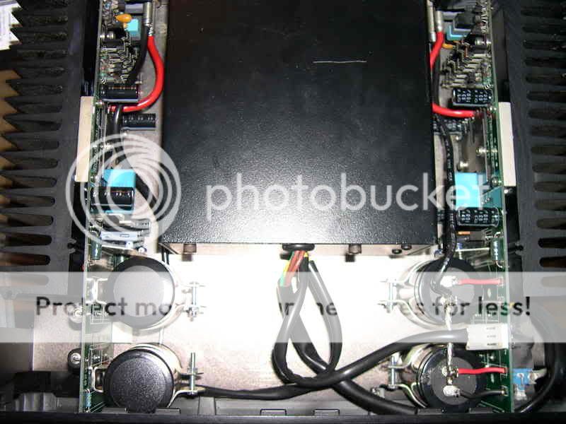
So, basically, I did the PS cap upgrade some time ago. All went fine except that there is now hum on the right channel and that I've lost the turn on-off protection (I can't hear any relay action). Unfotunately, this is not covered by the service manual. The sound seems not to be affected apart from this.
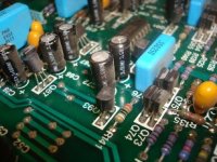
It turned out that the stock ground cable between the reservoir caps and the speaker connector is very hard to work with because it's thick, rigid and refuses solder. I wonder if my problems come from here. On the photo, you can see that the soldering, though firm, is not ideal. I plan to change the cable + connector very soon.
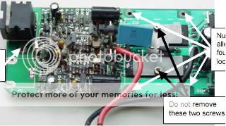
In the mean time, I will check other parts though I have no experience with transistors and have only a multimeter as a tool. I remember that I unscrewed the metal panel on the power transistor just to check them and it could have put out some of the compound (?).
Anyway experience form other users is appreciated, especially those who succeeded the cap upgrade. A great amp indeed!
Thank you
Alain

It turned out that the stock ground cable between the reservoir caps and the speaker connector is very hard to work with because it's thick, rigid and refuses solder. I wonder if my problems come from here. On the photo, you can see that the soldering, though firm, is not ideal. I plan to change the cable + connector very soon.
In the mean time, I will check other parts though I have no experience with transistors and have only a multimeter as a tool. I remember that I unscrewed the metal panel on the power transistor just to check them and it could have put out some of the compound (?).
Anyway experience form other users is appreciated, especially those who succeeded the cap upgrade. A great amp indeed!
Thank you
Alain
LK2-80 schematics
I do not know about tweaks but the LK2-80 has an interesting schematics.
Here some items I can notice:
1) Fully regulated power supply (even the output stage)...but the 1st and 2nd stage are not filtered from the output stage..
2) CFP output stage but with current mirror instead of usual resistor as load of the 1st transistor of the CFP.
3) "Split feedback" of some sort? FB1 goes back to 1st diff stage and FB2 (after complemetary VBE in CFP mode) goes to 2nd diff stage. Even the VBE multiplier seems to be connected to the output of the amp. Error correction? Is someone familiar with this topology what are the benefits?
And finally how does it sound or compare to other amps?
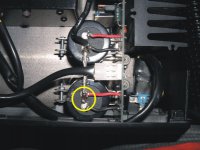
ACD said:This looks dangerously close to a shortcircuit
")
I know it does and it also look like dry solder, but it's not
Re: LK2-80 schematics
In my experience, it sounds better than UCD (I did an A/B test on mid and high freq, don't know about bass) and when I bought it about ten years ago it was really more lively and, may I say, straightforward than the Arcam and Rega amps in the shop.
fab said:And finally how does it sound or compare to other amps?
In my experience, it sounds better than UCD (I did an A/B test on mid and high freq, don't know about bass) and when I bought it about ten years ago it was really more lively and, may I say, straightforward than the Arcam and Rega amps in the shop.
Does anybody noticed the diodes connected pararelly with output emiter resistors (D12, D13 on the first schematic)? They can increase maximum output voltage. Emiter resistors can be bigger, so thermal stability is much better, and also they will dissipate much less power, especiallly when you use shotky diodes. I think that it can speed up output transistors, because when they are off (transistors), reverse base-emiter voltage will be smaller, so base-emiter capacitance will be discharged faster.
So many benefits, not any drawbacks, so why I see that first time. (I merely remember than i saw this before, but don remeber when ...). Please, correct me if im wrong.
So many benefits, not any drawbacks, so why I see that first time.
(I merely remember than i saw this before, but don remeber when ...). Please, correct me if im wrong. Re: Re: LK2-80 schematics
thanks for the info
kepa1 said:
In my experience, it sounds better than UCD (I did an A/B test on mid and high freq, don't know about bass) and when I bought it about ten years ago it was really more lively and, may I say, straightforward than the Arcam and Rega amps in the shop.
thanks for the info
Nobody corrected me... so I'll correct myself. First, these diodes will probably cause nonlinearity of output stage. It will cause some kind of crossover disortions, but in point where diodes turn on. Second, there is serious dangerous with thermal runaway. When voltage on emiter resistors will be close to 0.6V (due to bias current or due to small, not dangerous thermal effect), then if diodes turn on, thermal runaway will go very fast (emiter resistors will not be in effect). But this can be avoided by proper emiter resistors values - on choosen bias current voltage on that resistors should be at most at half of that turn diodes on.
Does anybody tried to compare that with classical output stage? Or at least tried that?
Does anybody tried to compare that with classical output stage? Or at least tried that?
Sorry Wojtek, this is beyond my understanding of electronics!
To complete my previous threads and aginst Linn advice
 , I have measured continuity across the power transistors pins and here are the results :
Q30 (upper left) : ec = 540 ohms cb : infinite eb = 0
Q34 : bc= infinite ce = 540 be = 0
Q24 : bc = infinte ce = infinite be = varies from 0 to about 70 - is that a short circuit ?
Q23 : ec = infinite cb = infinite eb = varies from 0 to about 70 ohms.
And I do find slightly different results on the other board
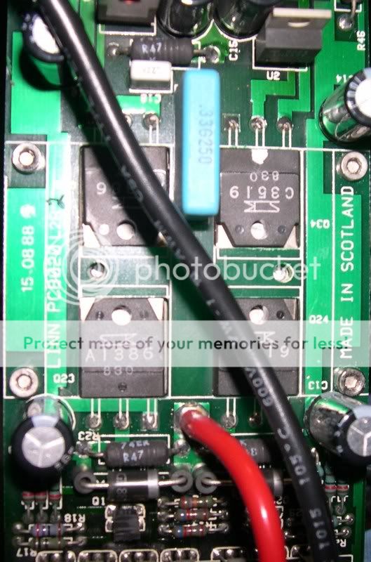
BTW the schematics above isn't 100% accurate since it uses different numbers for power transistors.
To complete my previous threads and aginst Linn advice
Q30 (upper left) : ec = 540 ohms cb : infinite eb = 0
Q34 : bc= infinite ce = 540 be = 0
Q24 : bc = infinte ce = infinite be = varies from 0 to about 70 - is that a short circuit ?
Q23 : ec = infinite cb = infinite eb = varies from 0 to about 70 ohms.
And I do find slightly different results on the other board
BTW the schematics above isn't 100% accurate since it uses different numbers for power transistors.
wojtek5001 said:Nobody corrected me... so I'll correct myself. First, these diodes will probably cause nonlinearity of output stage. It will cause some kind of crossover disortions, but in point where diodes turn on. Second, there is serious dangerous with thermal runaway. When voltage on emiter resistors will be close to 0.6V (due to bias current or due to small, not dangerous thermal effect), then if diodes turn on, thermal runaway will go very fast (emiter resistors will not be in effect). But this can be avoided by proper emiter resistors values - on choosen bias current voltage on that resistors should be at most at half of that turn diodes on.
Does anybody tried to compare that with classical output stage? Or at least tried that?
Thank yo ufor correcting yourself...
In fact, I was thinking about the same concern as you have but I was waiting for others for their comments...
But Linn is a serious company so I suppose there is a good reason for these diodes but what is it?
linn lk1
hello there,
as this is the thread closest to my problem I have thought that I might have a go at it.
I have bought a linn lk1 and lk2 system in uncertain condition; i.e. the items were sure to power up, but as the guy selling them did not have the connecting cables he could not test them. they looked ok, and I made some cables with coax wire for the connection from lk1 to lk2 myself.
testing the combination I found that both were working, but that the lk1 could not be turned down below about a third of its output power - which is way too much for most occasions. has anyone encountered the same problem and/or a possible solution?
thank you very much,
michael.
LK1 Parts List
I am encouraged that there are others who are working on Linn LK1 and LK2. I have a LK1 preamp that I want to "play with," but I don't have a parts list. I did find the service manual thanks to diyaudio forum. Do any of you have a LK1 parts list? And, from checking the service manual, the good folks at Linn state that some parts are obsolete. Is there any cross-reference to up-to-date parts? Any help is greatly appreciated! God bless your day!
I am encouraged that there are others who are working on Linn LK1 and LK2. I have a LK1 preamp that I want to "play with," but I don't have a parts list. I did find the service manual thanks to diyaudio forum. Do any of you have a LK1 parts list? And, from checking the service manual, the good folks at Linn state that some parts are obsolete. Is there any cross-reference to up-to-date parts? Any help is greatly appreciated! God bless your day!
LK1 Troubles
I appreciate kepa1's response, but I cannot respond to your email because I have not posted enough, even though I have been on board about three years! I have found some troubles with my LK1: The memory battery is bad (leaking juice!) and there are two swollen 22mf, 50v caps on the main board. Any help with parts would be greatly appreciated! Email me at rogerben@bellsouth.net please with a parts list.
I appreciate kepa1's response, but I cannot respond to your email because I have not posted enough, even though I have been on board about three years! I have found some troubles with my LK1: The memory battery is bad (leaking juice!) and there are two swollen 22mf, 50v caps on the main board. Any help with parts would be greatly appreciated! Email me at rogerben@bellsouth.net please with a parts list.
Attachments
May I ask you guys what the reason for the current hype around parts lists is?
You have the unit already open, so what's easier than to use a ruler to measure the diameter of the cap, its length (usually not even necessary as there's lots of space), have a look at its lead spacing, the ratings you already know, so here we go to order parts at Digikey or somewhere else.
If you're at it, redo for all electrolytic caps.
By the way I cannot see any swollen caps on the pic?
Have fun, Hannes
LK1 Troubles
I appreciate the fact that when I SEE a bad part I have no problem identifying it - provided it's not a completely burned resistor or a blown apart transistor, but I like to analyze the unit by studying the schematic and knowing the parts values helps. I'm not trying to be cute. It just helps to know what to look for. I read the color codes as fast as I read a book and not having a component layout makes it difficult to know where to look to isolate the problem to a particular section of the circuitry.
As far as "seeing" the swollen caps in the picture, I agree that they can't be detected by viewing it unless it is blown up from the original bit size. The score marks in the top of the cap are there intentionally: They allow the case to expand rather than explode. Knowing this design feature helps. The picture size restrictions do make it a bit difficult plus the 67 year old cameraman may not be the best either! But, replacing the two 22mf, 50v caps (C72 and C73 - filters for the + 15v and -15v in the MM section) did fix it. I have a 3-pin, 3.6v, 150mAHr Varta 3/V150H memory battery on order from Mouser Electronics for $11.98 plus S&H. The old one will not accept a charge past 0.7v and it is leaking.
Thanks for all your help. May God bless your day!
- Home
- Amplifiers
- Solid State
- tweaking classic Linn LK1 & LK2 / LK280