Hey there everyone.......
before i start let me give u a background........
i am a beginner in electronics........got an idea to assemble a Subwoofer based system for my PC..........planned to used two locally available kits( i'll mention them later).....planned to install a 4th order cross over (that i designed using TL074) and it works perfectlly......(lucky me...considering my knowledge).......
The Amp Kits
Well i purchased the kits using the circuit pretty much like the one in the link below
http://sound.westhost.com/project3a.htm
Well not exectly but the concept is same(Components values r
different even the transistors.)
Kit 1
To power a 12" Sub that would be placed in a transmission line Box.....the Kit has 2SD-1047 NPN power transistors.....PNP's not used......and vendor claims that it can handle two 12" subs(kit is two channel) but to a reasonable power.......having 0.47 5W output resistors
Kit 2
To power two 4" mids with tweaters for just the vocals, the smaller kit has 2N3055 output transistors.........pretty much like the above mentioned circuit
So Where the problem is????????
two questions to ask
1 Can Kit 1 be used in BTL mode by providing inverted signal to channel 2 and connecting speaker b/w both the outputs......Inverted signal will be provided by TL071...Would it really make a difference if only single channel is capable ov providin the power.......
2 Kit 2 with 2N3055 is heating too much at a resonable power output..they r good during normal biasing but when output is taken they start to reach SUPER NOVA....i have confirmed that the transistors are of low quality(fake) n planning to swap them with good ones(reletively better ones)......
What if i can replace them with MJ15003...a TO-3 package as well......read a lot abt them.......that they are better than 3055 but nowhere did i read that they are simple DROP-ON replacements so confusion here
Second problem is that there is not good heat conduction b/w 2N3055'S and there heat sink...a common heatsink for all four transistors.....well metallic conduction is avoided by an insulation layer ...a silvery thin cardboard type sheet b/w trans n heat sink......this might be probably causing overheating ov the transistors
yet heat conduction is there but transistor's capsule is much hotter....so a suggestion would be wise......yeah using separate heat sinks sounds a good idea but then again space inside Amp Chasis is not much...atleast i can give this idea a shot......advice needed here as well
Further Kit 2 is loading the SUpply a bit when pushed harder
Cant find any reason
To give some more info abt my prj.......the cross over is Butterworth 4th order 70 Hz...The TL enclosure is tuned for 40 Hz......In short an attemp to mix several things up. guys i am half way there....plz do the Needful
Some body would definatey ask...."What on Earth suggested u to go for a Transmission Line Sub"
The asnwer is reserved until asked
The final Question.......I used high current Diodes for Power Supply........they dont seem to heat even a single degree from Air temperature even when amp is pushed but they surely are causing 10V drop giving output close to 60v dc rather than 70 from a 25+25 V ac supply......SHould they be replaced for better perfromance or else.............
Kit 1 - would not advise it. Are you sure the 2SD1047 transistors are genuine, given that your 2n3055's arent? If they have really used 2SD1047 then emitter resistors shouldn't be required according to the data sheet.... I would be suspicious.
Kit 2 - FAKE 2n3055's? Wow, I didn't think anyone would bother!
You should be able to use MJ15003 as "drop in" replacements yes.. but if you have fake 2n3055.. you will probably get fake MJ15003 too.
The insulators you describe sound like mica washers. These need heatsink grease (the white paste) applied between all touching surfaces ie, on the heatsink, and on the transistor.
You might want to check that there is no conductivity between the heatsink and the metal cases of the transistors. If there is, then you will have a short circuit. The screws holding the transistors to the heatsink should have insulating washers.
Hi rustam54,
Jaycee has given you correct information. I agree totally with him.
I'd like to add a couple more points.
Avoid bridging an amplifier. Most don't react well and although they don't blow up, the sound isn't as clean it seems. The current will be about twice. That means a 4 R speaker "looks" like a 2 R speaker to both amps. You may get 3 ~ 5 dB more sound (not much), but only with a much larger power supply (at least twice the current).
2N3055 type transistors do not sound very good compared to the newer types and even the MJ15003 types. I would double the number of outputs for use in bridging per channel. This is both for the output transistor to be reliable and the voltage drop in the emitter resistors.
Real 2SD1047's are nice parts. I don't know how you can be sure if they are real if you are not experienced.
Why not buy complete kits from Elliott Sound Products?
-Chris
THanx u guyz......still further assistance required
hey ANATECH n JAYCEE.......
ur point is absolutely valid........but the problem is its not possible to buy the prebuilt circuit boards from abroad.......you have to stck up with either local boards....or design a new one for ur self that sounds a bit ummmmm costly...........
take it this way..........both amp kits r working perfectly (can say) but only a few hitches..........that i discussed above.......so i would be greatly obliged to all those who help correcting those problems.........may be the 2SD1047's arnt original......but can bear up a load to some extent............
well as ANATECH said.......bridging might pose some problems for me....in the long run...or may be initially......so i leave that part.......
the heat conduction problem will be resolved by using Mica sheet for the 3055......preiviously it was not mica but some other stuff..........
The problem is nobody in the local manufactures is willing to help me out......they say...."Sir, plz bring ur entire equipment to us n we'll do everything for u......" i dont mind getting it fixed from them......but i should give it a shot.......myself........this way i'll be able to learn more.......No matter if some transistors blow up n resitors turn to ashes...........i hace time for...at least one month before the vacations end........So........
DO advise......
Hi rustam54,
Mica is a good insulator. It must be used with a proper heat sink compound which is normally white in colour. I prefer this myself.
Do complete your project the best you can. When you buy your parts, make sure you are not using the cheapest store around. Try to use the larger distributors that have prices in line with what you see from the larger source pricing on the internet (like Farnell).
You can also use some of the newer On Semi parts for the 2SD1047, like MJl3281 or MJL21196 (I think that's the NPN).
-Chris
Guys.....a few more complexicities
Hey there Guys.......
A few more problems and some questions..........
Well the heating problem of 3055 was resolved...........allowing better heat conduction.....
But there is a problem.......
With the 2SD1047 kit.......the bass plays ok with the low pass filter ....... when tested using a 6" woofer without plugging in the small speakers or tweater in 3055 kit (connected to HPF)........
but when i plug in the mids or the tweater....the LPF starts to send some vocals in the bass............i checked the supply for the TL074....its good......but i cant figure that out..........
secondly the TONE CONTROL or PREAMP is sendind some noise........i figured may be that would be due to WRONG SHIELDING...........or may be due to the Transformer........
I doubt the transformer coz when i switch off the supply...i.e AC mains..........the system (running on the energy stored in the SUPPLY FILTER CAPS....10'000 uF each) produces clean O/p ......though for just a second........or 2....
i have used CHASIS ground for the entire system including the signal.....is it the correct way?????????
Lastly....one main point stuck in my mind when ANATECH replied to the thread............
can i parallel the output stage ov my 2SD1074 kit....... would then i'll be able to bridge it........dont consider the power from transformer.........it is 25+25 capable ov delivering atleast 6 amps continuous power.................and i have to power only ONE 12" sub through the kit
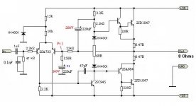
I have added the SCHEMATIC for my actual KIT............
If and only If anybody advised......i would provide the inverted signal to the 2nd channel at (Point1) through a 22k resistor from O/p ov first channel...........i saw it on P3A prj of ROD Elliot.........
or should i swap the O/p transistors.....does anybody here knows some DROP oN Replacements for 2SD1047........
Guys ......for u it might be a cheap amp to go for but it was the only one available to learn assembling ur own system
Hey there Guys.......
A few more problems and some questions..........
Well the heating problem of 3055 was resolved...........allowing better heat conduction.....
But there is a problem.......
With the 2SD1047 kit.......the bass plays ok with the low pass filter ....... when tested using a 6" woofer without plugging in the small speakers or tweater in 3055 kit (connected to HPF)........
but when i plug in the mids or the tweater....the LPF starts to send some vocals in the bass............i checked the supply for the TL074....its good......but i cant figure that out..........
secondly the TONE CONTROL or PREAMP is sendind some noise........i figured may be that would be due to WRONG SHIELDING...........or may be due to the Transformer........
I doubt the transformer coz when i switch off the supply...i.e AC mains..........the system (running on the energy stored in the SUPPLY FILTER CAPS....10'000 uF each) produces clean O/p ......though for just a second........or 2....
i have used CHASIS ground for the entire system including the signal.....is it the correct way?????????
Lastly....one main point stuck in my mind when ANATECH replied to the thread............
can i parallel the output stage ov my 2SD1074 kit....... would then i'll be able to bridge it........dont consider the power from transformer.........it is 25+25 capable ov delivering atleast 6 amps continuous power.................and i have to power only ONE 12" sub through the kit
I have added the SCHEMATIC for my actual KIT............
If and only If anybody advised......i would provide the inverted signal to the 2nd channel at (Point1) through a 22k resistor from O/p ov first channel...........i saw it on P3A prj of ROD Elliot.........
or should i swap the O/p transistors.....does anybody here knows some DROP oN Replacements for 2SD1047........
Guys ......for u it might be a cheap amp to go for but it was the only one available to learn assembling ur own system
Attachments
Hi rustam54,
Use the On Semi MJL or MJW parts to drop in for your 2SD1047. A bias adjustment will be required.
Keep in mind that all output devices are faster than 2N3055 types. Those are deadly slow and the 2SD1047 is so fast you may need to re-compensate your amplifier. Check out the SymAsym thread as they have gone through this with different output devices.
-Chris
Use the On Semi MJL or MJW parts to drop in for your 2SD1047. A bias adjustment will be required.
Right now you need an oscilloscope to check waveforms. You always need to check for HF oscillation when playing with amplifiers.but when i plug in the mids or the tweater....the LPF starts to send some vocals in the bass
Keep in mind that all output devices are faster than 2N3055 types. Those are deadly slow and the 2SD1047 is so fast you may need to re-compensate your amplifier. Check out the SymAsym thread as they have gone through this with different output devices.
-Chris
Bias Adjustments??????
Hi AnaTECH......
exactly what do u mean by Bias Adjustments........do i have to set the base bias voltages ov every transistor again....or just the power ones........
Plz if possible.........recommend some resistor values with the MJL's (that u mentioned above) CONSIDER MJL21195.......ALso suggest some good Driver stage transistors that i can put in......(Gaaash i dont even know what the driver stage is......Is it the 2SA733's or the 2SC945......or may be the 2SA684 and the 2SC1383 before the powers's?????i have no idea)
I have access to Oscilloscopes at my University......but couldnt there be another way.........i mean how can u check weather the NIOSE is due to magnetic field of the transformer........
Noise......I'll get it removed one way or the other.....
but i am eager to bridge it........
Despite your warnings (considering my knowhow).....plz give me one final word for Bridging.........
Should i parallel the output stage with multiple 1047's or should i try this after putting MJL's****
Your long unanswered question
"How am i gonna find original MJL's with the fact that 1047's and 3055's might be fake?????????"
ANSWER: The devices which are extensively used Locally are bound to be fake..........only if someone orders a local amp assembler a good quality Amp....only then they Put devices other than D1047's,,,,D313's ,,,,3055's........etc
So i am hoping to get Original MJL's......
PEACE!!!!!!
Hi rustam54,
The bias current adjust is the one variable control and will be described in your kit. You need to set the bias current no matter what. Just follow the directions.
You can try to "bridge" these if you want. I do not recommend this practice.
One last request. When you post, would you please use the shift key to produce capitals where they belong. That and speak in real words and structured sentences. This will make reading your posts much easier for the rest of us. Remember, many of our members do not speak English well. Give them a break and spell properly.
-Chris
The bias current adjust is the one variable control and will be described in your kit. You need to set the bias current no matter what. Just follow the directions.
Take your time and read your instructions for the kit. These sound like the drivers but only from your description, I haven't looked them up.or may be the 2SA684 and the 2SC1383 before the powers's?????i have no idea
You can try to "bridge" these if you want. I do not recommend this practice.
One last request. When you post, would you please use the shift key to produce capitals where they belong. That and speak in real words and structured sentences. This will make reading your posts much easier for the rest of us. Remember, many of our members do not speak English well. Give them a break and spell properly.
-Chris
Sorry for the Inconvenience
Hey there ANATECH
I would try my very best to write in structured sentences.....Thank you for the advice or correction.......
Now returning to the issue.........i was thinking of upgrading the system..........The KIT 1 i mentioned is infact similar to P3 of Rod Elliot (Not the P3A ........of which i have given the above link).....Sorry!!!!!!!!my mistake
Please do find time to see the original Schematic i have posted afterwards.......This is the current amp circuit.........
From now on......i am going to try the P3A circuit
Today i went to the Electronic Parts market and was shocked to find that OnSem's MJL or MJ series is completely unavailable........It took me 3 hours to search the entire market.......but Bad Luck.........
I am planning to modify the PCB of P3 to incorporate P3A.......(Bought new PCB today.......because i have no intentions to fiddle with the old one....it was cheap...)
But how to arrange for MJL-4281... MJL-21194...MJL-3281 or even MJL-21196...None of them is available....
So i did some searches and found 2sc3281 and 2sc5200.........reading at different threads i am convinced that 2sc3281 will be fake nowadays...though i can find some from used market (yes there is one)..........so the only option remains for 2sc5200.......
And please one more point to insist on......the 2SC**** parts are available in genuine state...thank God.......
But as you can see.......i need expert's green signal to proceed.......so what do u say.........anybody???????
Yes-Yes i know what you must be thinking.....how am i going to make another one without knowing how to fix the previous one.......i guess its all about faith")
two days ago i did'nt even know what quescent current is meant by ..........at least i know now.....may be things will open themselves up as time proceeds
Peace
Hey there ANATECH
I would try my very best to write in structured sentences.....Thank you for the advice or correction.......
Now returning to the issue.........i was thinking of upgrading the system..........The KIT 1 i mentioned is infact similar to P3 of Rod Elliot (Not the P3A ........of which i have given the above link).....Sorry!!!!!!!!my mistake
Please do find time to see the original Schematic i have posted afterwards.......This is the current amp circuit.........
From now on......i am going to try the P3A circuit
Today i went to the Electronic Parts market and was shocked to find that OnSem's MJL or MJ series is completely unavailable........It took me 3 hours to search the entire market.......but Bad Luck.........
I am planning to modify the PCB of P3 to incorporate P3A.......(Bought new PCB today.......because i have no intentions to fiddle with the old one....it was cheap...)
But how to arrange for MJL-4281... MJL-21194...MJL-3281 or even MJL-21196...None of them is available....
So i did some searches and found 2sc3281 and 2sc5200.........reading at different threads i am convinced that 2sc3281 will be fake nowadays...though i can find some from used market (yes there is one)..........so the only option remains for 2sc5200.......
And please one more point to insist on......the 2SC**** parts are available in genuine state...thank God.......
But as you can see.......i need expert's green signal to proceed.......so what do u say.........anybody???????
Yes-Yes i know what you must be thinking.....how am i going to make another one without knowing how to fix the previous one.......i guess its all about faith
two days ago i did'nt even know what quescent current is meant by
..........at least i know now.....may be things will open themselves up as time proceedsPeace
Hi rustam54,
Can you order from Farnell, Digikey or Newark? On Semi devices are available there with no troubles. I use Digikey mostly.
-Chris
Thank you. Much easier to read now.I would try my very best to write in structured sentences.....Thank you for the advice or correction.......
Can you order from Farnell, Digikey or Newark? On Semi devices are available there with no troubles. I use Digikey mostly.
-Chris
one more favour...please
Hi Chris,
i am not going to ask the same old questions again and again but this time........i do need you to look into it....its not difficult..........to look at data sheets
I was going to parallel the output stage.....but just then i read about two more higher rating transistors
2sc2922 and 2sc5200......i compared the datasheets with 2sd1047..........well 2sc2922 appears a good choice..........i compared the Vce-IC and Vbe-IC graphs in the datasheets as well...............what do you say????????????
For you suggestion to buy from Farnell...and differt other places.......i mentioned earlier that i do not have the option to order parts from abroad........a single transistor would cost me more than a Commertial amplifier.....i am not joking............
i only have access to Japaneese parts.......thats why 2SC series is easily available..........
Nauman...
Hi Nauman,
We have severe problems getting "real" Japanese numbers here. That's why I use On Semi. I have sources for the real parts. I love the Japanese parts.
To answer your question, the 2SC5200 seems to be the current choice. I have not used any due to the problems getting parts I know are real.
-Chris
We have severe problems getting "real" Japanese numbers here. That's why I use On Semi. I have sources for the real parts. I love the Japanese parts.
To answer your question, the 2SC5200 seems to be the current choice. I have not used any due to the problems getting parts I know are real.
-Chris
Well Chris i guess then...we both have a common problem......
I cant get US parts coz local importers dont do that......Japan is near geographically..................and like wise Japenesee ones are a problem for you........
Chris can i mount the power supply out ov the amp....in a seperate smaller body..........would long power cables affect it.....i mean even if i use thick wires......would the voltage drop be too high to affect..............
If not a problem......should i transfer AC or DC through the wire....i-e should i bridge it outside or in the AMP.....
The reason is my transformer is making my filters Noizy.......they sound okay with external supplies...............may be it is due to the fact that my filter circuits are close to the transformer....i'll try placing them elsewhere.....Wish me luck!!!!!!!
Nauman
Hi Nauman,
Is your problem with outside sources for parts one of duties and taxes by your government? I wonder how to solve this? I was hoping you could have ordered from some plac like Digikey and only had shipping to worry about.
So, sourcing parts. I have a suggestion. Collect the steros that go to garbage, or junk collection. Remove the parts from those because original ones will be real parts. I imagine you could get transformers and heat sinks as well then. Is this possible?
I ask because as a young boy, that is how I got my parts. Signal transistors used to cost me $3 ~ $7 CDN in the late 60's and early 70's. Junk was the only way to get parts. I can't tell how how many TV's I took apart and stripped (all tube types).
-Chris
I understand. Your mind is thinking and your fingers are typing fast to keep up.Sorry i made that structure problem again.....
Yes, this is a big problem for both of us then.Well Chris i guess then...we both have a common problem......
Is your problem with outside sources for parts one of duties and taxes by your government? I wonder how to solve this? I was hoping you could have ordered from some plac like Digikey and only had shipping to worry about.
So, sourcing parts. I have a suggestion. Collect the steros that go to garbage, or junk collection. Remove the parts from those because original ones will be real parts. I imagine you could get transformers and heat sinks as well then. Is this possible?
I ask because as a young boy, that is how I got my parts. Signal transistors used to cost me $3 ~ $7 CDN in the late 60's and early 70's. Junk was the only way to get parts. I can't tell how how many TV's I took apart and stripped (all tube types).
-Chris
Chris: My tranformer question
Hi Chris,
Can i place the transformer outside the main amplifier chasis in a separate chasis........
Or the losses will be too high...even with thick conductors......i plan to place the transformer 1.5 meter away....
The problem is that I can;t overcome the noise generated by magnetic coupling............eventhough i have checked for close ground looping in sheild signal wire.........the loop is open......i provide the ground from the signal receiving end.......
can the noise be intruduced at the POTs......because my variable resistor for Treble is directly infront of the transformer but there is a 4 inch gap.............
Secondly my 14 Volt supply (for the bass treble tone control and graphic display) is showing around 0.08 Volts AC.......may be it is because the rectifier and filter cap is mounted dirctly above of the transformer..............
Can u have a suggestion for this.......please dont mention the oscilloscope again.....its not available right now
Nauman
Hi Nauman,
As for your other noise, I do think you've got some excess leakage flux going on. That and your circuits need some shielding from the transformer. A larger case might be the proper answer here. Not the answer you wanted to hear. The other option is an external case. I really don't like that route, but you can try it simply to make sure it's not a grounding issue.
-Chris
I would rather you didn't. Mind you, any extra resistance in the supply would help lower the charging current peaks. That is helpful.Can i place the transformer outside the main amplifier chasis in a separate chasis........
As for your other noise, I do think you've got some excess leakage flux going on. That and your circuits need some shielding from the transformer. A larger case might be the proper answer here. Not the answer you wanted to hear. The other option is an external case. I really don't like that route, but you can try it simply to make sure it's not a grounding issue.
-Chris
- Status
- This old topic is closed. If you want to reopen this topic, contact a moderator using the "Report Post" button.
- Home
- Amplifiers
- Solid State
- Guys......Need help in an AMP Prj