Hi
I would like to make a balanced driver that more or less emulates the behaviour of a transformer.
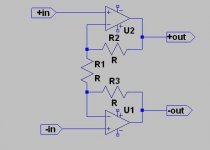
The "classical solution" shown in the picture has a problem in this respect: the output is implicitly referenced to the average of the two inputs, which means common mode from the inputs is transferred to the outputs.
I have found alternative circuits that fit the bill, for instance a difference amplifier followed by a unity gain inverting amplifier, but then the circuit is no more symetrical. I would like something more elegant, fully symetrical, as in the example.
Note that I don't need to emulate the floating output part of the transformer; I just need a reference terminal that sets the average output voltage independently of the inputs.
I'm pretty sure such a circuit has already been designed, but I can't find one.
LV
I would like to make a balanced driver that more or less emulates the behaviour of a transformer.
The "classical solution" shown in the picture has a problem in this respect: the output is implicitly referenced to the average of the two inputs, which means common mode from the inputs is transferred to the outputs.
I have found alternative circuits that fit the bill, for instance a difference amplifier followed by a unity gain inverting amplifier, but then the circuit is no more symetrical. I would like something more elegant, fully symetrical, as in the example.
Note that I don't need to emulate the floating output part of the transformer; I just need a reference terminal that sets the average output voltage independently of the inputs.
I'm pretty sure such a circuit has already been designed, but I can't find one.
LV
Attachments
If your levels and drive impedances will allow it, the classic simple solution is a one amp differential amp.
In its simplest form, it uses an opamp and four equal value resistors. The output WRT earth is equal to the difference between the two inputs.
Obviously, you can put the "instrumentation amp" circuit shown in your schematic above in front of a diff amp, and get an earth referenced output, and still have high input impedances.
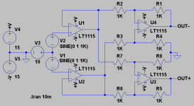
suzyj said:That's easy.
You just need a pair of diffamps, connected in mirror. Plenty of common mode rejection:
OK, it's symetrical and it does the job....
but I have a sort of a gut feeling that it should be possible with only two opamps (and this sort of feeling is rarely wrong).
You might remember that I tend to produce minimalist designs...
Thanks anyway
LV
Things are getting interesting:
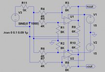
I followed my instinct and tried to eliminate the buffers from Suzy's circuit.
I did that by adding two resistors, R9 and R10. They are negated by their connection to the opposite output and cancel the input resistance presented by the difference amplifiers. It works fine: the voltage across the input current sensing resistor R11 is now 0, meaning the input impedance is infinite.
BUT, this is the differential impedance: quite surprisingly, the common mode impedance is 3K for each of the inputs.
This is the analogue of a perfect center-tapped transformer whose tap is grounded via a 1K5 resistor. Quite interesting and potentially very useful, but now I would like to find a rational design method to determine the resistors, taking into account the gain, differential impedance and common mode impedance (by manipulating the values, it is certainly possible to also cancel or assign any arbitrary value to the common mode impedance).
Of course, there is always the brute force solution of writing and solving all the equations of the circuit, but there has to be a smarter and more intuitive method.
Any idea?
Attachments
- Status
- This old topic is closed. If you want to reopen this topic, contact a moderator using the "Report Post" button.
- Home
- Amplifiers
- Solid State
- Balanced amplifier alternatives