I'm trying to figure out the maximum device dissipation for an output stage with 4 devices (2 +ve, 2-ve). Assuming supply rails of +/-48V and an 8R load (also assume resistive only), would the maximum peak device dissipation occur at 22V? On my calcs, the load current would be 2.75A, resulting in peak dissipation per device of 30.25W ( (48-22)*2.75A/2). If I was using a 0.4Deg/W heatsink, this would amount to a temperature rise of 25 degrees per pair. Is this the correct way of calculating max device dissipation? What other factors do I need to take account of?
Thanks
Thanks
I would suggest the following articles are worthy of a good read:
http://sound.westhost.com/patd.htm
http://sound.westhost.com/soa.htm
http://sound.westhost.com/patd.htm
http://sound.westhost.com/soa.htm
Hi Smithy,
a number of other calcs to take into account.
1.) de-rate the device for elevated temperature.
if the Ts =30degC (almost cold) and Tc=40degC then de-rating for a plastic package is [150-40]/[150-25]=0.88. So a 100W device can dissipate a continuous 88W IF YOU CAN KEEP Tc=40degC.
for Tc<=87.5degC de-rating factor = 0.5 This allows a sink operating temperature upto about 75degC.
2.) de-rate the device for elevated voltage. You must consult the datsheet to see at what voltage the device starts to enter second breakdown. At Vrail=48V some devices are down to just 50% others are still up at 95%.
3.) you need to combine the two de-rating factors from above.
4.) de-rate the heatsink for reduce delta T.
Most manufacturers specify their sink dissipations for a sink temperature between 70 and 80Cdegrees above ambient. If your delta T (Tsink-Tambient) =40Cdegrees then the de-rating can be about 1.2 to 1.4 consult the manufacturer's datsheet on dissipations for this factor for their sinks.
5.) the speakers are reactive. I find that one can model the worst case fairly closely for first selection but doing the following.
Take Vrail and multiply by the peak current into your nominal load. This gives the peak dissipation into a 45degree phase angle load, moderate rather than severe. Now compare this peak dissipation to the de-rated power from 3 above.
6.) once some possible devices AND heatsink are identified, one can start to do the manual calculations, which are quite extensive, to ensure your devices never exceed the one shot dissipations that the manufacturer specifies/guarantees in the datasheet.
Amp design is not back of the fag packet stuff, it involves real arithmetic. Once the experts have done a few dozens of complete amp designs, they get quite good at instantly assessing requirements, us mere mortals have to go the long route until we can build up sufficient experience.
smithy666 said:Is this the correct way of calculating max device dissipation? What other factors do I need to take account of?
Nope
=> a heatsink calculation requires RMS values.
=> max rail voltage due to mains surge and transformer regulation.
Hi Richie,
he is referring to the DC output voltage. That is hardly a valid AC requirement.
For AC signals the maximum average dissipation occurs when the output voltage is much closer to maximum than half voltage (50%) and higher than half power (70%). More like 75% to 80%.
Can someone tell us the actual % of maximum voltage to develop worst case dissipation for a sinusoidal waveform into a resistive load?
A lot of usefull discussion about SOA and dissipation issues, also with reactive loads, can be found here:
Burr-Brown AB-39: POWER AMPLIFIER STRESS AND POWER HANDLING LIMITATIONS
APEX App Note 1: General Operating Considerations
(Sections 7.1 & 7.2)
APEX App Note 22: SOA and Load Lines
Those deal with power operational amplifiers but there is no difference in the output stage compared to discrete amplifiers.
The app note section at apexmicrotech is a good resource on a variety of topics relevant to power amplifier design, that's why I recommend it quite frequently.
http://eportal.apexmicrotech.com/mainsite/support/pages/app_notes.asp
For sinusodial AC into resistive loads, the maximum device dissipation appears when the peak AC output voltage reaches 63% of the supply voltage, to answer the specific question. And that's for class B (or AB with very low bias current) and freq>50Hz.
Regards, Klaus
Hi,
I too expected the peak voltage to be much higher.
Ktsr's links clearly show the 63% figure.
Uncle,
your 56% of power is 75% of voltage, 21.21/28.28Vac = 30/40Vpk= 0.75
A +-60Vdc supply is more likely to produce an amplifier of 150W maximum output.
You would also need to measure the sag in the power rails when the amp is actually delivering the near half maximum power.
What does high/low bias current do to typical worst case dissipation values? An extreme example; a ClassA amplifier runs cooler as soon as one asks it to deliver any power to the load.
The typical rule I would use for a low bias ClassAB continuous duty would be dissipation~=60% of maximum output power.
The peak output voltage for max dissipation is 63% of PS voltage, but the instantaneous voltage is about half of the PS voltage for most of the cycle. Doesn't this mean that the 63% figure is used to calculate peak dissipation - in which case would you use the current at this point and multiply by the half the supply rail to get worst case dissipation for a resistive load?
AndrewT - that question has also crossed my mind about bias current, but I had assumed you would add this to the operating power for total dissipation. Is this correct?
AndrewT - that question has also crossed my mind about bias current, but I had assumed you would add this to the operating power for total dissipation. Is this correct?
Hi Smithy,
I have not tried to calculate what happens with quiescent dissipation over a range of output powers. But if we take a very simple case.
Re=0r1, 2pair output stage, maximum output power ~100W, +-50Vdc supplies, Vre=25mV, Ibias =0.5A (optimum ClassAB) Pq=50W, Pmax~=60W,
I suspect that the dissipation to the sink starts at 50W when zero signal is present and falls to a minimum just as the output current has risen to 1Apk (the ClassA output limit) and then rises again to that 60W figure and finally falls very slightly at maximum output.
Somebody will be clever enough to simulate that for us.
The resistive load is effectively a waste of time. It happens to allow us to compare for testing purposes but that's about as far as useful.
Reactive loads are much more severe when considering instananeous dissipation.
I use half peak current times Vrail as an indication of instaneous power in the output devices for a 45degree phase angle load. Unfortunately some loads are worse than this. Bensen's spreadsheet shows it well.
simulation can be more illuminating than spreadsheets
LtSpice is free, can easily calc, display peak power, built in function for ave device dissapation
this sim shows several Spicey power calcs:
from:
http://www.diyaudio.com/forums/showthread.php?postid=1161042#post1161042
LtSpice is free, can easily calc, display peak power, built in function for ave device dissapation
this sim shows several Spicey power calcs:
jcx said:... a sim that calcs device power when the load current phase angle varies - approximating a complex impedance load]
sim can do this too, LtSpice calcs device pwr (hold down alt after tran analysis, click on device body when thermometer appears)
E = sine Voltage
Z = impedance magnitude
phase = load phase angle (degrees) - stepped from 0 to 90 in 30 deg increments
approx slightly off from using independent Isource as load but close enough for most purposes
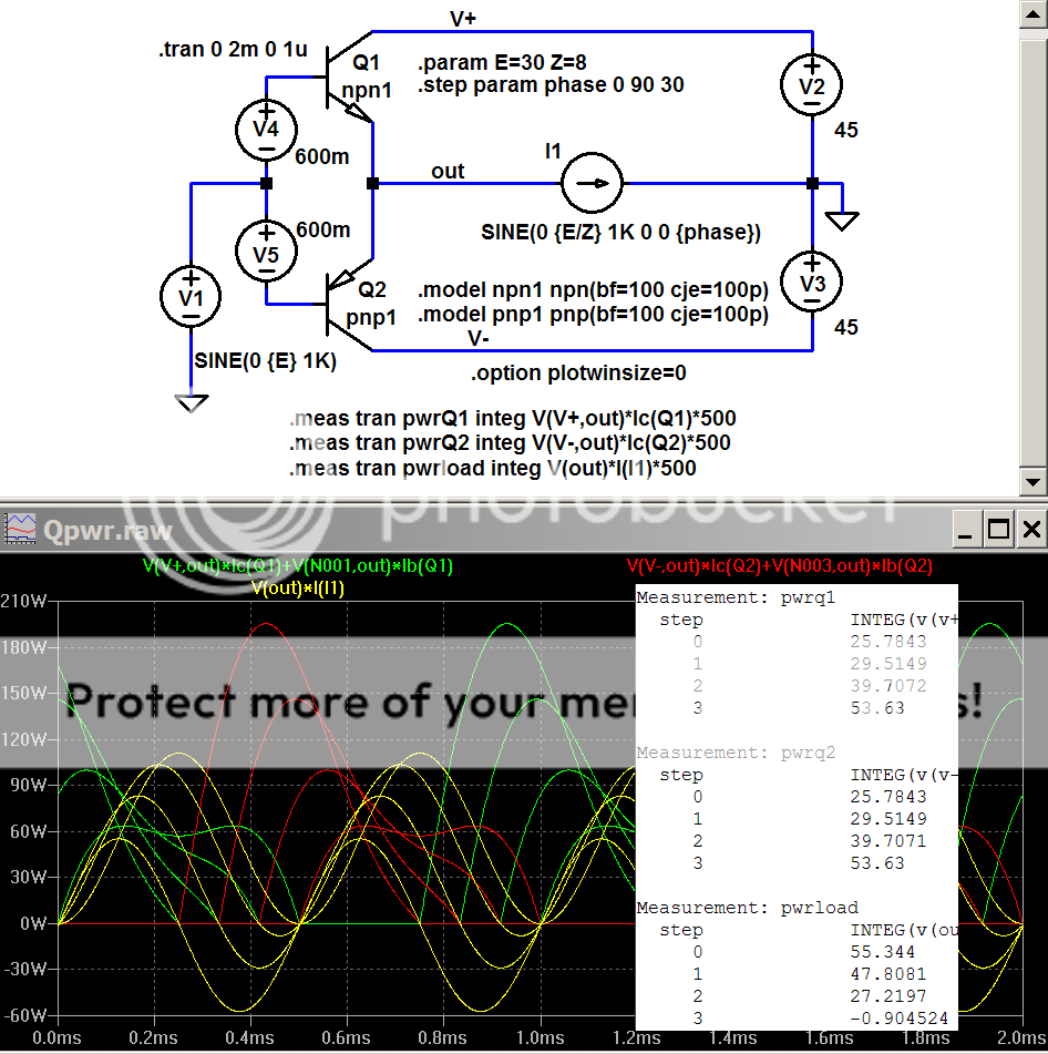
The huge peak device power with 90 degree (pure imaginary) load is clearly visible in the plots
LtSpice file, runs in free Linear Technology Switchercad iii
http://www.linear.com/company/software.jsp
(rename without .txt)
from:
http://www.diyaudio.com/forums/showthread.php?postid=1161042#post1161042
Attachments
Aside from cost, it's space & weight & complexity & matching &....
One of our regular posters has a 9pair output stage in his amplifier.
I have just built up a 6pair output stage.
It is much more complex to wire up than a 3pair output stage and the whole mechanical design is dominated with attempting to remove heat and the conflicting requirement for compactness.
A little question.
How would one know if they have added sufficient extra pairs?
- Status
- This old topic is closed. If you want to reopen this topic, contact a moderator using the "Report Post" button.
- Home
- Amplifiers
- Solid State
- Maximum device dissipation