anatech said:Hi Bee C.,
From me earlier ....
Right now your gain is attempting to be infinite, or open loop with only DC feedback in practical terms. In any event, it's not going to be a happy amp without some gain here.
I haven't looked that far into your amp. I just know there are some very basic things you need to get right first. Run at a lower voltage until it's running, then reduce the bias current and raise the voltage. Reset your bias current at this new voltage.
-Chris
") Heee..he...he...
Heee..he...he...The PIC looks good.I can save to JPEG format
but How to insert thge image on to the text ?
Anatech u mind i should add the series resistor like this ?{attach image}
Attachments
Bad Picture ???
The Picture is
Too bad .....
Bee C. said:
The PIC looks good.I can save to JPEG format
but How to insert thge image on to the text ?
Anatech u mind i should add the series resistor like this ?{attach image}
The Picture is
Too bad .....
Attachments
I'm SORRY.........
I'm sorry anatech...
I'm on offday last two days....u know ?!
I'm only can make a connection on my workhshop at my office.....
Hee....he.....I'm not as u think.......

Thank for all you have make me up ......... The amp. under construction...I'll tell u if I had done.....soonnnnnnnnn........
btw the scheme be like this one ?!
anatech said:Hi Bee C.,
Oui!
That's what I meant. The degeneration resistors may not be required. That is fine tuning. Get it working first and only change one thing at a time (so you know what worked and what didn't).
-Chris
I'm sorry anatech...
I'm on offday last two days....u know ?!
I'm only can make a connection on my workhshop at my office.....
Hee....he.....I'm not as u think.......
Thank for all you have make me up ......... The amp. under construction...I'll tell u if I had done.....soonnnnnnnnn........
btw the scheme be like this one ?!
Attachments
Hi Bee C.,
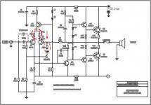
Q5 and Q6 need to be exchanged, Q7 and Q8 should be exchanged also. They are the wrong polarity for their position. That is to say that MJ15003 and 2SD313 are NPN while MJ15004 and 2SB507 are PNP. They would surely blow if connected the way you have shown.
Use a fixed resistor for RX3. Remember this sets your amplifier's gain along with R6.
-Chris
Bleww up....

You too sharp in this..........
thank's againn..again....but I'm on my office so when I come home i'l make it up....
It's good enought to have 100w at 8ohm if I give 30v ?
How exactly I can get current an or the voltage for the driver ? How if the final Tr I use TIP41C/TIP42C ?
Is the R6 as "bosstrap" ?
anatech said:Hi Bee C.,
Q5 and Q6 need to be exchanged, Q7 and Q8 should be exchanged also. They are the wrong polarity for their position. That is to say that MJ15003 and 2SD313 are NPN while MJ15004 and 2SB507 are PNP. They would surely blow if connected the way you have shown.
Use a fixed resistor for RX3. Remember this sets your amplifier's gain along with R6.
-Chris
You too sharp in this..........
thank's againn..again....but I'm on my office so when I come home i'l make it up....
It's good enought to have 100w at 8ohm if I give 30v ?
How exactly I can get current an or the voltage for the driver ? How if the final Tr I use TIP41C/TIP42C ?
Is the R6 as "bosstrap" ?
Attachments

Hi Bee C.,
You need approximately 50 volt supplies to deliver 100 watts into 8 ohms. You would also require two pairs of strong output transistors such as MJ15022 and MJ15023 or MJ21193 and MJ21194 to safely deal with out of phase current and stay winthin the SOA of your outputs. Your drivers needs to be stronger. TIP41C and TIP42C are extremely borderline there, more like MJ15030 and MJ15031 for those. I have not checked your VCE specs on the rest, but they should be rated for at least 120 VDC.
R6 is the resistor that provides your feedback signal, it's a series loss element to drop the voltage along with R3.
-Chris
crawlll....
Thanks anatech...
if the R6 is a feedback resistor and can bee losses the voltage...if it's scure to take away the RX3 ?!
Anatech...the MJ15003/15004 is too expensive for mee.... ...he...he.....I'll break my piggy bank for this one....
anatech said:Hi Bee C.,
R6 is the resistor that provides your feedback signal, it's a series loss element to drop the voltage along with R3.
-Chris
Thanks anatech...
if the R6 is a feedback resistor and can bee losses the voltage...if it's scure to take away the RX3 ?!
Anatech...the MJ15003/15004 is too expensive for mee....
...he...he.....I'll break my piggy bank for this one....Hi Bee C.,
Perhaps you should build for lower power in that case. A blown amplifier is not useful to anyone.
I can say that good quality, matched outputs and driver transistors do reduce distortion. Build within the limits of your circuit and use the best parts you can reasonably afford. That may mean a 50 watt amplifier using the original parts list. It's only 3 dB going to 100 watts, so you will not miss much at all.
-Chris
Greattt....
Chris...
if I should say u...
I have an appetite whit BIG Power Amp. but...I have'nt much money to braek my dream come truee...
the only I can do is what like u said.....
btw...I wondering if u have suggest for software what can I use for modeling amplifier/any circuit..for knows the right or wrong whit the circuit assy ?!
is "Eagle" good enought ?
anatech said:Hi Bee C.,
Perhaps you should build for lower power in that case. A blown amplifier is not useful to anyone.
I can say that good quality, matched outputs and driver transistors do reduce distortion. Build within the limits of your circuit and use the best parts you can reasonably afford. That may mean a 50 watt amplifier using the original parts list. It's only 3 dB going to 100 watts, so you will not miss much at all.
-Chris
Chris...
if I should say u...
I have an appetite whit BIG Power Amp. but...I have'nt much money to braek my dream come truee...
the only I can do is what like u said.....
btw...I wondering if u have suggest for software what can I use for modeling amplifier/any circuit..for knows the right or wrong whit the circuit assy ?!
is "Eagle" good enought ?
Hi Bee C.,
You are talking to a guy that designs the circuit by hand, then designs and builds the PCB. Then it either works or it doesn't and once I have figured that out, I make a new PCB and rebuild it.
I really do have to figure out how to use these new fangled software packages. I did use Orcad a long time ago. It takes longer to design the circuit, but it becomes easier as you make revisions. I still wasn't that impressed.
For artwork, I used the rub down patterns on clear film. The clear film was laid on top of 10 div / inch graph paper. It was positive artwork and always worked very well for me. The design phase was pencil on the same 10 div / inch paper.
-Chris
Cooll....
Hii Chriss...
I salute for You and every one whom make their own pcb by hand....a hand made.....

I remember my first pcb what I make when i'm on junior high school..( smp-here )...I mark the stripe lines whit a felt-tip marker....it's too "hard" for me ( I'm not good wit stright line drawer)...and I ettach whit a cloroferitch ?! ( I'm not sure to spelled)..... haa..ha...ha.... that was so great time....
I serching for software like psipce ?!
but i cant used,right know I have a "Eagle v.4.16" not familiar for me....hee..he...
the first software i used is Workbench.....I forgat the version.....
it's helfull to simulate the circuits.....(for me i think)...
but I lost the cd's.....(

Bee C.
Hii Chriss...
I salute for You and every one whom make their own pcb by hand....a hand made.....
I remember my first pcb what I make when i'm on junior high school..( smp-here )...I mark the stripe lines whit a felt-tip marker....it's too "hard" for me ( I'm not good wit stright line drawer)...and I ettach whit a cloroferitch ?! ( I'm not sure to spelled)..... haa..ha...ha.... that was so great time....
I serching for software like psipce ?!
but i cant used,right know I have a "Eagle v.4.16" not familiar for me....hee..he...
the first software i used is Workbench.....I forgat the version.....
it's helfull to simulate the circuits.....(for me i think)...
but I lost the cd's.....
( Bee C.
Hi Bee C.,
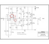
Have you been following the DX Amplifier thread, because the DX Amplifier is very close to your final circuit. The lessons learnt there may help you avoid some of the potential problems, i.e. I would suggest you change the biasing diodes to a Vbe multiplier mounted on the heatsink.
Eagle is certainly good enough for schematics and PCB design, but it doesn't have spice built in. You may want to have a look at the DX Amplifier PCB because it would take only a few modifications to fit your design. Doing a good layout is very time consuming, so if you have something to start with, your half way there.
R8, R9 and C4 form the "bootstrap". R6 is part of the feedback circuit anatech has been talking about.
regards
Hi Greg,
Thanks for your input in the DX amplifier thread. I haven't read it yet.
Still, there is the problem that I and many other members face when a board needs to be made. How to get that lovely pattern out of the computer and formed in copper. Some of the laser to photo paper and iron on ideas sound attractive. Much better for people like me who no longer have a steady hand.
-Chris
Greg Erskine said:Hi Bee C.,
Have you been following the DX Amplifier thread, because the DX Amplifier is very close to your final circuit. The lessons learnt there may help you avoid some of the potential problems, i.e. I would suggest you change the biasing diodes to a Vbe multiplier mounted on the heatsink.
Eagle is certainly good enough for schematics and PCB design, but it doesn't have spice built in. You may want to have a look at the DX Amplifier PCB because it would take only a few modifications to fit your design. Doing a good layout is very time consuming, so if you have something to start with, your half way there.
R8, R9 and C4 form the "bootstrap". R6 is part of the feedback circuit anatech has been talking about.
regards
Hiii Greg.....
Thanks for your post.....
I some agree whit u ,I try to learn at the DX amplifier thread......
that's nice amp..... but not cheep for me.....
so what software i cab use for analyze the circuit ?
could u send me the software ? to : be_cek@yahoo.com ?????
I'll greath tahnks for u greg.....

Best regards,
Bee C.
Bee C. said:Thanks for your post.....
I some agree whit u ,I try to learn at the DX amplifier thread......
that's nice amp..... but not cheep for me.....
so what software i cab use for analyze the circuit ?
could u send me the software ? to : be_cek@yahoo.com ?????
I'll greath tahnks for u greg.....
Hi Bee C,
I am also looking for some circuit analysis software as well.
regards
- Status
- This old topic is closed. If you want to reopen this topic, contact a moderator using the "Report Post" button.
- Home
- Amplifiers
- Solid State
- Help COLD OCL 300W Burn....