Please I've get burned the Final Transistor ( 2N3055 / MJ2955 ).....had 32V at output ( SPK ) whit input dc +/- 38V.....
It's an old stuff at my junked......i tried to rebuild but keep burn the C2,C4,C5 (47uf/50V)
I'M CONFUSED................
Please tell me what I've to do ?!
Many thank's

It's an old stuff at my junked......i tried to rebuild but keep burn the C2,C4,C5 (47uf/50V)
I'M CONFUSED................
Please tell me what I've to do ?!
Many thank's
Attachments

Hi Bee C.,
Please check the extension of your file name. There is a list of file types accepted. The size must be less than 100 KB.
The other method is to host the file and attach the url.
BTW, those outputs transistors are normaly only good for 60 VDC C-E. Therefore a maximum supply of + / - 30 VDC, 25 VDC to have some headroom. There were some that were supposed to be good for 100 VDC. I don't trust them.
-Chris
Old RCA units could hold that voltage...i can remember that very clear.
Than appear 2N3771 and 2N3773.
Those old RCA were excelent...i think you were too much young those days dear Anatech.
Then appeard the alluminium case Motorola units...those ones awfull!
We still make them in Brasil... a big company that started producing supplies to old computers using 2N3055 already produce them in this country. brand is SID
regards,
Carlos
Hi Carlos,
Unfortunately I do remember the original Lambda 2N3055 transistor.
It was spec'ed at 60 VDC C-E (I say that because many people look at the C-B voltage rating and it was often higher), 115W and an F-3dB of 19 KHz. It was originally designed as a power supply pass transistor and the low Ft was so it wouldn't oscillate when mounted on a heatsink with wire away from the PCB. Motorola manufactured the original I'll bet, and it was an accurate device under their name.
The others that followed should have had a different number as the specs were completely different. They weren't great parts but at least put up with higher voltages. This didn't make them a better part - in fact they were worse for the original application.
These days I hope one would use an MJ15003 and MJ15004 instead of the ancient 2N3055 and MJ2955. 2N3773 and 2N6609 were another good pair (this from memory! I need help!!!). 2N3771 was a low voltage, very high current device, 30 A was it? I think 2N3772 was a 20 A device (now I know I'm old!!).
Carlos, did I surprise you?
-Chris
Thank you!Those old RCA were excelent...i think you were too much young those days dear Anatech.
Unfortunately I do remember the original Lambda 2N3055 transistor.
It was spec'ed at 60 VDC C-E (I say that because many people look at the C-B voltage rating and it was often higher), 115W and an F-3dB of 19 KHz. It was originally designed as a power supply pass transistor and the low Ft was so it wouldn't oscillate when mounted on a heatsink with wire away from the PCB. Motorola manufactured the original I'll bet, and it was an accurate device under their name.
The others that followed should have had a different number as the specs were completely different. They weren't great parts but at least put up with higher voltages. This didn't make them a better part - in fact they were worse for the original application.
These days I hope one would use an MJ15003 and MJ15004 instead of the ancient 2N3055 and MJ2955. 2N3773 and 2N6609 were another good pair (this from memory! I need help!!!). 2N3771 was a low voltage, very high current device, 30 A was it? I think 2N3772 was a 20 A device (now I know I'm old!!).
Carlos, did I surprise you?
-Chris
Re: Old RCA units could hold that voltage...i can remember that very clear.
I still have some Motorola aluminium 3055.
Thought to build an ancient-style amplifier with them, sometimes...
Whats wrong with the aluminium types?
regards
Jürgen
Hi Carlos,destroyer X said:
Then appeard the alluminium case Motorola units...those ones awfull!
I still have some Motorola aluminium 3055.
Thought to build an ancient-style amplifier with them, sometimes...
Whats wrong with the aluminium types?
regards
Jürgen
They used to be very bad.... maybe fake ones
Also they have no big weigth.... to me, they gave me the idea that were made with empty boxes...no weigth! ...ahahahahah.
Those ancient days, early days, my friends used to tell me... go down town and buy 2N3055 made by RCA only, do not buy those aluminium things Motorolla made!
I had many of those ones burned, the idea of fragille was associated, since those days, with those units.
Also some of them warped...and not a good heat contact with the heatsink.
Fragile leads too...if move them they broke inside the piece.
You may say they could be fake..... yes.....maybe because of that...it is possible, but i could find some samples, inside plastic bags, into television station technical place, Motorola guaranteed parts, sold to Ampex, with the same characteristics...i am not sure the ones i remember, as bad ones, if they were original or not.
regards,
Carlos

To : anatech...
Thak's for ur solution I know I new here sorry for the pic mybe i have a bigger file than 100kb...but I currently see if the pic just about 84kb, I drawing whit Visio and safe the file in *.JPG and *.gif format......
is there a simple explain for me....I'm a stupid in class....he..he....
if i give the rail/input about +/- 38Vdc it's supposed to be fine in mine ?! not get burn the Capsitor or the Transistor ?
To : Destroyer X
in my country it's hard to find the Transistor......not cheap is the reason ?!
btw thank's guys......
I still get the Elco 47u/50V blew......
Thank's
Thak's for ur solution I know I new here sorry for the pic mybe i have a bigger file than 100kb...but I currently see if the pic just about 84kb, I drawing whit Visio and safe the file in *.JPG and *.gif format......
BTW, those outputs transistors are normaly only good for 60 VDC C-E. Therefore a maximum supply of + / - 30 VDC, 25 VDC to have some headroom. There were some that were supposed to be good for 100 VDC. I don't trust them.
is there a simple explain for me....I'm a stupid in class....he..he....
if i give the rail/input about +/- 38Vdc it's supposed to be fine in mine ?! not get burn the Capsitor or the Transistor ?
To : Destroyer X
Than'ks for your solution...but...Than appear 2N3771 and 2N3773.
in my country it's hard to find the Transistor......not cheap is the reason ?!
btw thank's guys......
I still get the Elco 47u/50V blew......
Thank's
Hi Bee C.,
Also, check the driver transistors and also the resistors, especially the low value ones.
The problem is that many people don't understand between the 60 V parts and the 100 V parts. Therefore it's best to simply avoid them all together and use parts that are well known.
BTW, there is nothing wrong with the Motorola aluminum parts. I've used ton of them over the years. I like the beefed up areas to take the pressure. I never once had a problem with them bending or leads breaking. I have seen the leads broken due to mishandling. I think I used them all up now.
-Chris
Well, 38 VDC X 2 is 76 VDC. If you have an original 2N3055, it will only be guaranteed to withstand 60 VDC, or + / - 30 VDC supplies. Use MJ15003 and MJ15004 for replacements, or if you had 2N5631 and 2N6609 you can use those.if i give the rail/input about +/- 38Vdc it's supposed to be fine in mine ?!
Also, check the driver transistors and also the resistors, especially the low value ones.
The problem is that many people don't understand between the 60 V parts and the 100 V parts. Therefore it's best to simply avoid them all together and use parts that are well known.
BTW, there is nothing wrong with the Motorola aluminum parts. I've used ton of them over the years. I like the beefed up areas to take the pressure. I never once had a problem with them bending or leads breaking. I have seen the leads broken due to mishandling. I think I used them all up now.
-Chris
You see juergenk, it is probable that mine units were fake
As Anatech had replace hundreds of units and had not problems.
So, relax with your aluminium transistors...be happy!
Oh dear Anatech, even knowing you love those beefy parts...sorry, they were awfull...say...those enlarged parts.... it seemed a guy with a 5 inches chin!
regards,
Carlos
As Anatech had replace hundreds of units and had not problems.
So, relax with your aluminium transistors...be happy!
Oh dear Anatech, even knowing you love those beefy parts...sorry, they were awfull...say...those enlarged parts.... it seemed a guy with a 5 inches chin!
regards,
Carlos
Attachments

Hi Carlos,
I've seen many things.
The funniest were those aluminum transistors with Japanese markings and number. A really, really bad fake.
-Chris
I've seen many things.
The funniest were those aluminum transistors with Japanese markings and number. A really, really bad fake.
A different market. Yours certainly may have been fakes. I'm very careful to buy from proper distributors, close to head office in North America. Fakes were rare.As Anatech had replace hundreds of units and had not problems.
-Chris
You so Kind....
Many thank's for you anatech.......And for the others in the treads...
.....
You're open up my mind...
I'll send my file to your's give me the advise and don't blame me for the schem....he..he..ha.....
I'll check again whit all the driver ( BD139/140 ) and olso to try change the 2N3055/MJ2955 whit MJ15003/MJ15004.....it's hard to find the original from Motorola in my teretory....I'll try n try......
Thank's to all of u..
keep it up .....
Be_cek....
anatech said:Hi Bee C.,
Would you please send my your file? bhomester at gmail dot com.
-Chris
Many thank's for you anatech.......And for the others in the treads...
.....
You're open up my mind...
I'll send my file to your's give me the advise and don't blame me for the schem....he..he..ha.....
I'll check again whit all the driver ( BD139/140 ) and olso to try change the 2N3055/MJ2955 whit MJ15003/MJ15004.....it's hard to find the original from Motorola in my teretory....I'll try n try......
Thank's to all of u..
keep it up .....
Be_cek....
Hi Bee C.,
It's a Visio schematic. You would have to save it in a jpg format to post it here. I only have the viewer. It's also 193 KB, so too large to post.
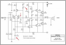
C2 requires a resistor in series to set your feedback ratio. You should have zero bias with a three diode string across your driver bases. This design is beyond what a pair 2N3055 compliments will handle. It's pushing MJ15003 and MJ15004. With a 0.5 R emitter resistor you really would be better off with two pairs of outputs.
Is this an existing amplifier, or are you trying to build one from scratch? You should have a look at the SymAsym if you are trying to build one. There are some good clues there as well.
-Chris
It's a Visio schematic. You would have to save it in a jpg format to post it here. I only have the viewer. It's also 193 KB, so too large to post.
C2 requires a resistor in series to set your feedback ratio. You should have zero bias with a three diode string across your driver bases. This design is beyond what a pair 2N3055 compliments will handle. It's pushing MJ15003 and MJ15004. With a 0.5 R emitter resistor you really would be better off with two pairs of outputs.
Is this an existing amplifier, or are you trying to build one from scratch? You should have a look at the SymAsym if you are trying to build one. There are some good clues there as well.
-Chris
anatech said:Hi everyone,
Attached the schematic finally.
-Chris
Edit: The 4148 diodes are the wrong type. The voltage drop may be much higher here and they may easily short or go open. Use 1N400X types.
Thanks anatech......
I'm sorry for the visio .....
For the Di and D2 I some agree whit u....
Some friend here give me another clue :
Change the driver whit : BD131/B507(original is BD139/BD140) and the protection TR ???
change from D438 to BD139 ....... the final tr is used MJ15003/MJ15004....?! ...
...I'm not so sure whit is....

Ceerssss
Bee C.
Hi Bee C.,
From me earlier ....
I haven't looked that far into your amp. I just know there are some very basic things you need to get right first. Run at a lower voltage until it's running, then reduce the bias current and raise the voltage. Reset your bias current at this new voltage.
-Chris
No problem. You use what you have and what is comfortable for you. Can you save in JPG or JPEG format?I'm sorry for the visio .....
From me earlier ....
Right now your gain is attempting to be infinite, or open loop with only DC feedback in practical terms. In any event, it's not going to be a happy amp without some gain here.C2 requires a resistor in series to set your feedback ratio.
I haven't looked that far into your amp. I just know there are some very basic things you need to get right first. Run at a lower voltage until it's running, then reduce the bias current and raise the voltage. Reset your bias current at this new voltage.
-Chris
- Status
- This old topic is closed. If you want to reopen this topic, contact a moderator using the "Report Post" button.
- Home
- Amplifiers
- Solid State
- Help COLD OCL 300W Burn....