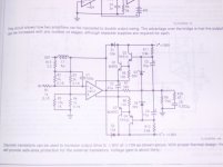
this is something i found on national book based on lm12clk
considering that is powered on rails of 100volts should produce a hell of lot of power ...
any body ever build a thing like that ????
opinions are very welcome
thank you ......sakis
east_electronics@yahoo.gr
considering that is powered on rails of 100volts should produce a hell of lot of power ...
any body ever build a thing like that ????
opinions are very welcome
thank you ......sakis
east_electronics@yahoo.gr
Attachments
thanks conrad gaetan
well yes true i ve was playing in the past but only once with lm 12 but the particular part was very terrible i think made may be in bulgaria very cheap so i can really tell
gaetan .... to my understanding this schematic will easily produce 200 w @ 8R the question is there a schematic with lm3886 and or other that can easily produce this kind of power ????
can lm 3886 be "boosted " with outside transistors ?????
there is a topology if remember well from original sgs books and tda 2030 boosted with a pair of BD911-12 ....this i tryied produces some 40-45w on the bench but its extremelly stable and very dynamic also .....
could this have simular behavior ????
Note that the LM12 is operated permanently out of 36V lines local to it and that the rest of the voltage drop is on the xternal darlingtons. Also note what the load resistor is! Even though the principle is sound, operating a low mpedance load with the attached schematic is not likely, think of the SOA required from the external parts.
Tried a boosted LM3886 in 2006.
I tried the LM3886 with external transistors , similar to the TDA2030 scheme. This seems to be quite an old circuit as I remember seeing it long ago ( late 70 's ? ) in Wireless World. That application was with opamps.
Anyway , the FFT distortion plot of the amp was much inferior compared to the stand alone LM3886 within its own ratings ( without external transistors) . So I dropped the idea of trying to use it. The odd order went up quite a lot. Maybe it can be tweaked further to improve the performance.
However it certainly works. I played it too and I can't remember too well how good it sounded . But I can say that it certainly didn't sound bad . My reason for dumping it was the poor FFT that I got !
I did think up of some other component changes but never got round to trying it. I plan to do it some time soon as the original boards and heat sinks are still around.
Note that I built only one channel and ran it at +/- 35 volts into two 8 ohms speakers in parallel ( effectively 4 ohms with dips to 2.9 ohms) . It drove them happily without any strain until the normal clipping point. Even slightly clipped it was good. Meaning that mild clipping didn't cause the sound to go to pieces. The heat sinks got very hot. Interesting enough to follow up and tweak.
Cheers.
true.....
i was thinking the same ilimzn and yet the lm 12 stand alone requiers a lot on cooling and stability considering thermals but also pcb design versus ocilation locally created and good routing between in and out ......
stil i am willing to try and especially now that it seems nobody else did....from the previous aplication i ve been runnig i.e tda 2030 boosted with bd 912+11 i know for shure that this amp loves inductive loads and it was very stable even driving speakers or transformers in 100v application
i will produce something i call surface mount pcb that gives me thermal stability .... in a few days .... will see
the good think is that i can have many of lm 12 clk .....and in good prize also he he he so will see how its going
Re: thanks conrad gaetan
Hello
Yes, find the an1192.pdf file, use google to find it.
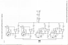
There is a parallell-bridge 200watt version of the lm3886 in that file.
Here a small image of that schematic.
Gaetan
sakis said:well yes true i ve was playing in the past but only once with lm 12 but the particular part was very terrible i think made may be in bulgaria very cheap so i can really tell
gaetan .... to my understanding this schematic will easily produce 200 w @ 8R the question is there a schematic with lm3886 and or other that can easily produce this kind of power ????
can lm 3886 be "boosted " with outside transistors ?????
there is a topology if remember well from original sgs books and tda 2030 boosted with a pair of BD911-12 ....this i tryied produces some 40-45w on the bench but its extremelly stable and very dynamic also .....
could this have simular behavior ????
Hello
Yes, find the an1192.pdf file, use google to find it.
There is a parallell-bridge 200watt version of the lm3886 in that file.
Here a small image of that schematic.
Gaetan
Attachments
thanks andrew t
no thats not right ...the resistor of 750 R is part of the drive .... true i noticed also strange topology on this schematic ....
out is on the left side just right after the out coil
please let us know what do you thing about that ......
thanks gaetan for the bridge to bridge and bridge from bridge and bridge plus bridge schematic i am just truing to make a joke ..... may be possible that this produces some 200w but i dont like it from topology not the kind of thing i like to do .....
but thanks though
no thats not right ...the resistor of 750 R is part of the drive .... true i noticed also strange topology on this schematic ....
out is on the left side just right after the out coil
please let us know what do you thing about that ......
thanks gaetan for the bridge to bridge and bridge from bridge and bridge plus bridge schematic
i am just truing to make a joke ..... may be possible that this produces some 200w but i dont like it from topology not the kind of thing i like to do .....but thanks though
i will be ...
be building very soon this with tda and aditional bd 911-12 just to listen to and remember how this thing is playing be fore constructing the lm 12 thing .....
my pcb is ready to go to the print house then will see ... i think ive done a very odd job
will mount everything on heatsink .....
then solder the pcb directly to transistors (using it upside down ) and then solder the rest of components like smd .....
here is a view ...
Attachments
guys ......
give me a brake ...... this original schematic from national
what do i do ????? ignore the book?????
it doesnt say that you design that with 10 pairs of transistors
then whats the point on having it to the book ???? as what??? as sugestion ???
dont get it ......
still eager to construct will see
thanks though for the interest ....andrew t i thing you have a very nice sense of humor ..... it is not easy to write this post cause i am laughing my brains out..... thanks though .....i will construct nomatter ....and post my results
thank you people
to richie boy
Post #14
Only one pair of TO-220 helper transistors? What voltage will you be using, and what load?
the two 220 transistors are only the drivers of mj 802 and mj4502 that boosting the lm 12
as about the rail voltage .... the book says 100 beatyfull volts .....the book from my view there is not much else to say
give me a few days and i will let you know
if andrew t is right will post my labs postal adress so all of you can send me fire extinguisers for birthday resent can use them also in some other amplifiers that failed to construct .....
people who follow my post know very well what i am talking about
will find out ...
pcb is on the way..... just a few days and we will find out ......
i got a hinch from my guts that this will operate like his small brother tda 2030 boosted with bd 911-12 i.e will have power of some 150-200w on the bench but have dynamics of almost the double .....or more
i like diy audio glossary destroyer x have big love for sonics i have crazy love for dynamics !!!!!
richie00boy said:That original app note shows what appears to be a single pair of output transistors and 90V rails driving 10 amp loads. Even though I'm seeing it I can't believe it.
Orginal app note says: " with proper thermal desing" (read: "-273 Celsius, or plenty of liquid nitrogen")
1pair of output transistors can probably handle thermal dissipation with music signals. Problem is still that output devices SOA is smoky...narrow.
ok
all these you say i take very serious but still its in the book !!!!!
thermal mangement DO not mean adding of 10 pairs of transistors .... but proper and equall cooling of the all set ...i think also my theory is crap so i just think.....
will see as i said lets give it a few days
funny thing so many people constructed so many things but none so far messed up with a thing like that
- Status
- This old topic is closed. If you want to reopen this topic, contact a moderator using the "Report Post" button.
- Home
- Amplifiers
- Solid State
- powerfull schematic