"And you may use it only after a voltage divider otherwise you risk cooking your amp."
Technically, this is not correct.
A zener requires a ballast to work properly.
For DC this is usually a resistor.
For AC it may be a resistor or a reactive component.
A reactive component is better because it dissipates negligible power. The crossover capacitor serves as a reactive ballast.
Technically, this is not correct.
A zener requires a ballast to work properly.
For DC this is usually a resistor.
For AC it may be a resistor or a reactive component.
A reactive component is better because it dissipates negligible power. The crossover capacitor serves as a reactive ballast.
The crossover capacitor serves as a reactive ballast.
Could still lead to amp overload. I would still use it after a voltage divider (L-pad) which ight be necessary anyway except the midrange is a horn as well or another very high efficiency driver.
Regards
Charles
I'm sorry you don't understand the idea of a reactive ballast,
I definitely think that I do. As a chartered engineer I could even derive the necessary matematical description without consulting any book.
But that does still not mean that I must like it, does it ??
Regards
Charles
"I will use -18db tweeter crossover network before this circuit.
Is this ok?"
Klipsch made hundreds of thousands of the type AA networks that used an 18dB tweeter crossover with zener diode protection. They were used in the Klipschorn/Belle/and LaScala, as well as various pro-sound models. The zener diode protector was also available as an add-on for the Heresy and Cornwall, the type E and B network board already had a place with a hole in it for the diodes.
Klipsch discontinued using the diodes in the mid 80s largely for cost reasons. They switched to using the RayChem PolySwitch (less than 1/10th the cost), but had a lot of problems with failures after that. The whole story behind the change is quite complex. Another thread could be opened if you want all the
details.
You could use the diodes in conjunction with an L-pad, but remember, the resistors will get hot, where the reactive components will not. Klipsch used a tapped inductor to lower the levels, not resistors.
djk:
I am interested from the academic point of view. Also i might require to make for 2" compression driver. This will also increase my knowledge about the subject. So ur thread/ideas r most welcome.
Another thread could be opened if you want all the details.
I am interested from the academic point of view. Also i might require to make for 2" compression driver. This will also increase my knowledge about the subject. So ur thread/ideas r most welcome.
"I am interested from the academic point of view. Also i might require to make for 2" compression driver. This will also increase my knowledge about the subject. "
"I am also waiting 4 ur details/new thread about the klipsch protection circuit"
OK, let's keep on with it here for a while.
Drivers fail for two reasons:
Excess average power
Mechanical damage
Clipping will not hurt anything if it does not cause the above problems.
After larger amplifiers (above 50W) became common, problems with high frequency units self-destructing became a problem.
A tweeter like the EV T35/Klipsch K77 could handle 5W continuous, 50W for 10mS peaks, so normal program material wasn't the problem.
The tweeters were dieing from mechanical failure. The voice-coil was wound with aluminum wire that ran out to the terminals on the frame (self-termination). Shallow slopes in typical crossovers (6dB) combined with higher drive levels produced failures. Copper wire was tried instad of aluminum (aluminum work-hardens in a very short time).
Still, the failures continued.
Klipsch switched to the 18dB crossovers in the very early 70s. This helped with the excursion failures.
Now, 100W+ amplifiers became common.
Klipsch went to cathode-to-cathode connected zener diodes. These clipped off the peaks that were mechanically destroying the tweeters. Things went well for about ten years.
In the early 80s it was time to try and get rid of the expensive band-aid (the zener diodes). EV changed the lead-out wire from the self-terminated copper voice-coil wire to a flat BeCu wire like used on expensive JBL and Altec type compression drivers. A new network was designed with an elliptical filter with 50dB of attenuation only a half-octave away from the crossover point. A fast- acting instrumentation fuse was added.
Problem solved?
The new version of the tweeter used a UV cure adhesive vs the old thermo-set adhesive. After the fuses blew from modern program material (about the same time as the introduction of the CD), they got replaced with fast-blow types (which offered reduced protection). The special instrumentation types were very expensive, and very hard to find.
The new UV cure adhesive got soft, bubbled, and failed quite easily.
A PolySwitch was tried. Too slow.
The old thermo-set adhesive came back.
The combination of the super-steep crossover, the flat BeCu lead-out wire, and the PolySwitch seemed to work (with the old adhesive).
The zener diodes were retired for mainly two reasons: cost, and limited dynamic range. The AA networks used a pair of 5.1V 10W zeners. These only allowed about 2W RMS through before they started clipping off the peaks (a 4W peak square-wave) .
With the advent of digital program material, 2W of undistorted program material no longer seemed adequate (about 97dB at 10 foot). The zeners limited the maximum distorted output to about 100dB at 10 foot.
Removal of the zeners allowed exploitation of the 50W/10mS rating of the tweeter, about 14dB more output capability (referenced to the 2W RMS zener clamp).
What did EV do for products sold under their brand?
The STR tweeter protector was developed for this use. Later it was modified by adding a lightbulb in parallel with the relay contacts.
I hope this give a little insight into what is needed for tweeter protection, and how we got to where we are.
Vifa, Dynaudio, and others offer a choice between self-terminated tweeter lead-outs and a braided (or tinsel) type lead-out.
The difference in cost for the braided type is worth it in my book. Most manufacturers of lower-priced product do not spend the money for this, or better crossovers either (although I am seeing lighbulbs and/or PolySwitches in some inexpensive product).
Crossovers and tweeters must be designed to avoid mechanical damage in normal use (correct slope, frequency, and lead-out wire for the intended use).
Long-term thermal protection is worthwhile. Some sort of switch device (relay, PolySwitch, fuse) in conjuction with a lightbulb seems to be the most cost-effective. Due to the long time constant of lightbulbs, most use does not seem to demand the switch (which shorts out the lightbulb in normal use).
Suggested current levels:
For 1" coils (tweeters), about 1A. The 561 or 211-2 automotive lamp has worked well in this application.
For 1-3/4" coils (1" compression drivers), about 2A. The 1156 type automotive lamp has worked well in this application.
For 3" (kapton) to 4" (nomex) coils (2" throat 16 ohm compression drivers), about 2A. I have found a 1.5A AGC (or 3AG) type fast-blow fuse will pass 400W of program material in normal use, and blow almost instantly if bad feedback is encountered. A pair of 1156 automotive lamps wired in series with each other, and then wired in parallel with the fuse will allow the show to go on when the fuse blows, and still offer some protection. If the fuse blows in the course of normal use, you need additional HF drivers, horns, and amplifiers.
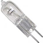
I hv recently seen halogen bulbs used as protection in some crossover pcb.
I want to use it for Paudio 750 model.
The compression driver is rated for 100W.
The easily available halogen bulbs are 12V/20W & 12V/50W.
Is this bulb ok to use?
If yes, then 20W or 50W, which will be more suitable?
I want to use it for Paudio 750 model.
The compression driver is rated for 100W.
The easily available halogen bulbs are 12V/20W & 12V/50W.
Is this bulb ok to use?
If yes, then 20W or 50W, which will be more suitable?
Last edited:
dJk
The bulb is 10mm round by 28 mm in height ( glass size).
The picture is attached herewith.
Normally the operator is trying to get maximum output.
The amp will be say 600W~800W for 4 compression drivers.
But the signal is boosted by mixer.
Hence consider more safety.
The bulb is 10mm round by 28 mm in height ( glass size).
The picture is attached herewith.
Normally the operator is trying to get maximum output.
The amp will be say 600W~800W for 4 compression drivers.
But the signal is boosted by mixer.
Hence consider more safety.
Attachments
Those have a 2.84" (72mm) Nomex former voicecoil, and will handle about 40W long term.
Power is I^2*R, so the limit is about 2.236A RMS.
A #1156 lamp is 2.1A nominal at 12.8V, that's pretty close. These will take momentrary transients of 17V or so, so I would use two in series with the driver. This should offer good protection up to inputs of around 325W/8R (600W/4R). Mic feedback shouldn't be a problem unless sustained for more than a few seconds, and then one of the bulbs may blow.
Neither of your bulbs seems suitable. A 36V 2.236A (80W) bulb would be fine, but I know of no such part.
Eminence make a range of passive crossovers which are good quality.
These include light bulbs for tweeter protection.
http://www.eminence.com/crossovers.asp
The lightbulb is situated as the first component in the Hi-Pass filter.
I would think that the position of the bulb before the hi-pass filter is significant.
I know of people who have had good reliability from a 45W tweeter using the eminence crossover, even when driven at 500w RMS (crossover point was 3K5 hz 18db/octave).
In my experience blown tweeters are usually the result of a clipping amplifier.
The square wave harmonics will quickly overload the HF Driver.
If this is the case here, a signal limiter before the power amplifier will pay for its self.
Thanks djk.
U hv explained in very nice & easy manner.
So the tweeter is only just 40W in long term use.
VC = W.
17.889 v x 2.236A = 40W.
If i use one 12V/ 20W halogen bulb, then the dc resistance will be 7.2 ohm & current 1.66A. Hence we need to pass more .7A current. If we put 18 ohm 10/20W resistor in parallel, will it serve the purpose?
Only preference for halogen bulb is it's compact size.
- Status
- This old topic is closed. If you want to reopen this topic, contact a moderator using the "Report Post" button.
- Home
- Amplifiers
- Solid State
- tweeter ( Compression driver) protection circuit