AKSA said:Hi Pooge,
Resolution is intimately related to noise levels. A moment's thought shows that any noise will mask low level detail; if this detail is spatial information/cues, then the imaging will suffer. Keep the noise down and awareness of the sound space will increase. However, it's not so hard keeping noise down on power amps, the big challenge is vinyl preamps, and generally, for MC, one needs to use JFETS to achieve this.
Hugh
When I was thinking the other week about what I how I would describe what was important to me in an amp, the first thing that came to my mind was resolution. Then I tried to think about how to define that. While I hope I don't divert a thread about Cdom by discussing it too much, my definition of resolution ended up with a list of many other subjectively good qualities wrapped up in the same package. I could go on and on, so I'll quit here.
AKSA said:
When you examine the pole constraints on stability, you find that group delay on a SS amp amounts to one half the periodicity of the waveform at the pole frequency. Most are around 500KHz, so this implies 180 degrees of phase shift at this frequency with roughly linear phase shift up to the point of instability.
Thus, we have a propagation/group delay around 1uS, and at 20Khz, this is 7.2 degrees.
Since we are hearing much diminished harmonics, if at all, at this frequency, it follows that at say 5KHz, a more realistic upper limit to the musical artefacts, we have less than 2 degrees of phase shift as signal passes through the amp. This phase shift will be more pronounced the higher the frequency, and this is the problem....
It's too late to wrap my head around this, even if I could follow your train of thought. Whenever I see a discussion like this, I usually bypass it, because when one discusses phase shift and group delay like it's inherently bad, I don't know if they are equating it with distortion. There is an inherent time delay in an amp. If it is equal at all frequencies, or flat group delay, which is a good thing, there will, by definition, be more phase shift at higher frequencies; which is not a bad thing, because it is an equal time delay. It is not distortion. A single pole creates a 45 degree phase shift at the pole frequency, and no more than 90 degrees at higher frequencies. 1us seems awfully slow for an amp. It should be on the order of nanoseconds, and the deviation from linear phase shift (phase distortion) should only be on the order of a couple of degrees at 20kHz, so I am not following your discussion.
AKSA said:I confine my comments to amps, not to speakers, but you make a very good point, essentially that much more reward would be forthcoming if we minimised cone/VC mass and maximised force factor. Presumably only this, discounting the impedance mismatch of the driver/air interface and troublesome back reflections from the enclosure, would reduce phase shift at the driver.
[/B]
While I don't disagree with you here (you are describing my horns, which are merciless at revealing everything sent to them), my reference to resonance in a loudspeaker is more akin to cone breakup or the like, where all sound seems to come from the same location, rather than at distinct locations. To use an analogy of the effect of a screen door as visual noise, it stays in one location while you can clearly see a 3D image behind the screen which moves as you move. But a reasonance may collapse that 3D image into the plane of the screen, and it won't move in relation to the screen as you move.
AKSA said:Phase shift on speakers is hugely important; it can deviate easily 10 or 15 degrees across the crossover point if the filter is not correctly designed. We've found that changing out resistors can impact on this phenomenon, and there is nothing magical about this as a phase plot on a good software package will demonstrate very clearly. And this does create palpable imaging anomalies. On a recent two way TL design, we managed to get it down sub one degree each side of the crossover at 2500Hz.
You should be able to compensate for this effect by altering the inductors slightly - a quarter or half turn should do it.
And the round, metallised caps, the Solens, have considerable self inductance - showing the entire crossover is a compromised system and tweaking is essential once the raw dimensions drop out of the forumulae.
[/B]
Not sure if you are talking different resistor values or different resistor type. The changes I referred to were different types of the same value.
While the Mills resistors in the speakers are non-inductively wound while the ones I replaced were not, my hunch is that the inductance was not the issue; but I really don't know. I say this because the changes did not seem so related to frequency response issues, or timber, as much as better focus and separation of detail, etc.
As far as the I/V resistor goes, I got less noise amplitude (lower hiss level), and the timbre of the hiss seemed to change. (Now put me a blind test of the before and after, and I may get shot down.) However, wirewounds do have the potential of lower noise than metal films, so maybe I did hear a difference. But it does make me think of making space for more wirewounds on a PC board.
steve_mak said:I'm hoping it will work out!
Annihilate all desire - Mahatma Ghandi
Which path are you actually going to follow?
")
AndrewT said:The output offset set trim could be fitted to vary the VAS current, or on the collector load of the LTP, or a DC current injection into either the inverting or non-inverting input. There can be a variety of others if you're ingenious, eg, SKA, but I can't divulge that one, it is simple and clever.
Is this simple clever method also better than most? I've seen quite a few amplifiers that use the method of injecting a small bias current from a supply rail into the + or - ltp input. This can be done with one resistor so it would be hard to get simpler than that. However, this sort of approach might also degrade the amplifier performance if the bias current is contaminated with power supply noise. I recently built a dc offset corrector that used this method but Instead of a resistor I used a current source and added (after some trial and error) enough temperature compensation to track the amplifier's DC drift. This requires a few components but seems to work well and holds the offset to < 3 mV. This gets around the requirement for an active controller which is more complex and can have unwanted side effects.
However, if there are better ways it would be nice to get some +fb.
David
Your simplified approach undoubtedly works well, but as you said, takes a lot of trial and error. Unfortunately, you would probably need to change the configuration and component values for each individual amplifier.(or channel ?)
An active offset controller can be made to work quite transparently, particularly if you use 2 separate time constants at it's input. The first time constant being much smaller than the second. You can also split the output resistor into 2 sections, with a small capacitor from the centre to earth. This has the advantage of attenuating any HF noise that may influence the overall performance of the amplifier .These resistors are of course MUCH higher value than the LAR of the NFB network. .
SandyK
Re: compensation capacitor Cdom
O.K. that was too rudimentary to just load the current mirror with a 20Meg resistor. Nevertheless, the improvement is just not marginal.
I struck on an idea today. {I am using the following buffer stage inbetween the LTP/Current Mirror and VAS stage. The transistor is a 2N5401. Emmiter resistor is 820E. Collector Zener is 16Volts and the limiting resistor value is 2K2. The top line you see is the 63volts +ve rail. The Base is driven from the LTP and drive to the VAS is from the Emmiter. (This is an adaptation of an idea given to me by Anthony Holton). I see a lot of noise in a simulator due to the zener but in practice I found the buffer to be very transparent sonically compared to a few other types I have tried.}
I will load the unloaded side of the Current Mirror with one more buffer as shown and ground the emmiter with a suitable resistor. At this point I have no idea what the value of that resistor should be but it should approximate the impedance presented to the emmiter of the buffer by the VAS. Any comments?
Yes, the input HF filter is formed by a 330pf cap and 27k resistor. I may be able to reduce the value of the cap to somewhere between 270pf and 220pf to increase the bandwidth.
The Miller cap right now is 39pf. It is made of a 27pf+12pf, both silver mica types. I may try to reduce this to 27pf; 22pf is another value that I have, but I am worried about stability with such a reduced Miller cap value.
One more enquiry: Any comments on bootstrapping the input as shown by D.Self in his Load Invariant Amp, in as far as noise and sonic performance is concerned.
O.K. I have the buffer circuit as a .TIF. I need to change this to an acceptable form. So I'll post this in a subsequent post.
sandyK said:Sam
I only suggested that resistor , because it was a simple thing for someone else to try. It was based on a guesstimate of the HFE of the transistor loading the other side, and it's bias current. It is not the method that a couple of us use.For best results you need the temp coefficient of a diode in there too.Now that the soundstage is further improved, have a look at your front end input filter. Can it be given a higher rolloff frequency ? Bandwidth increase should bring back the sweetness and give further improved localisation of instruments and voices. You may even be able to slightly reduce the value of what this topic is all about. Don't use a ceramic capacitor.Use a suitably rated polystyrene.
I am not prepared to further elaborate to anybody who just wants to stick things in a Simulator and say the result is a load of crap, and just another "Blameless and Sterile" D.Self clone !
I have been there, done that. I have been trying to get other people to try with an open mind since 1987.
Thanks for taking me seriously Sam. Remember that the LTP transistors should be closely matched for HFE AND VBE, preferably thermally coupled too.
SandyK
O.K. that was too rudimentary to just load the current mirror with a 20Meg resistor. Nevertheless, the improvement is just not marginal.
I struck on an idea today. {I am using the following buffer stage inbetween the LTP/Current Mirror and VAS stage. The transistor is a 2N5401. Emmiter resistor is 820E. Collector Zener is 16Volts and the limiting resistor value is 2K2. The top line you see is the 63volts +ve rail. The Base is driven from the LTP and drive to the VAS is from the Emmiter. (This is an adaptation of an idea given to me by Anthony Holton). I see a lot of noise in a simulator due to the zener but in practice I found the buffer to be very transparent sonically compared to a few other types I have tried.}
I will load the unloaded side of the Current Mirror with one more buffer as shown and ground the emmiter with a suitable resistor. At this point I have no idea what the value of that resistor should be but it should approximate the impedance presented to the emmiter of the buffer by the VAS. Any comments?
Yes, the input HF filter is formed by a 330pf cap and 27k resistor. I may be able to reduce the value of the cap to somewhere between 270pf and 220pf to increase the bandwidth.
The Miller cap right now is 39pf. It is made of a 27pf+12pf, both silver mica types. I may try to reduce this to 27pf; 22pf is another value that I have, but I am worried about stability with such a reduced Miller cap value.
One more enquiry: Any comments on bootstrapping the input as shown by D.Self in his Load Invariant Amp, in as far as noise and sonic performance is concerned.
O.K. I have the buffer circuit as a .TIF. I need to change this to an acceptable form. So I'll post this in a subsequent post.

Alex (sandyk) sent me few tips. I tried them and have reported my observations to him. In short, I was able to get my already modified Quasi Mosfet amp to perform very close to my Stochino amp, which is the best I have heard so far, including diy and commercial amp.
If Alex gives some details here, I will expand a bit more.
If Alex gives some details here, I will expand a bit more.
compensation capacitor cdom
Samuel
Have you fitted your regulated front end supply yet ?
This should give a further improvement, due to a further improvement in overall noise level.
(Samuel initially tried 2 x 10Megohm resistors in series between the collector of the differential pair on the unloaded side, and the adjacent supply rail for the current mirror In this case 20Megohms highlighted there was an improvement possible, as there was an emitter follower fitted. In cases where there is no emitter follower between the differential pair and the VAS, a lower value resistor could be tried. Perhaps, initially try 10 Megohm, or even 4.7Megohm)
Also, with the differential pair balancing, the soundstage and overall SQ will markedly improve when the difference voltage
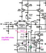
between the collectors of the well matched differential pair is reduced below 5 millivolts, However, measures may need to be taken to stop drifting away from the optimum. These measures will depend on the actual circuit, but various options include 1. Replacing the tied B and E junction of the current mirror with a 1N4148 diode. 2.Cutting the PCB track between the collectors of the differential pair and current mirror, on the unloaded side of the current mirror and inserting a 1N4148 diode,and if needed a small schottky diode in series, to give the necessary voltage drop. In the case of my Class A amplifier , it was approx. 900mV.
.Fine tuning of the collector difference voltage may be performed by varying SLIGHTLY the value of the emitter follower,or VAS emitter resistor to achieve balance. If the loaded side has in effect the equivalent of 2 base emitter junctions in series loading it (1.2V) then 3. a series 1N4148 diode and resistor may be used. This diode will also give thermal compensation. The value of the resistor needed will be equal, in this case to half of the overall resistance equivalent of the loading of the base current of the EF/VAS stage. The bias current is approximately the collector current of the loading transistor divided by it's HFE. It may be possible to use a 10Megohm trimpot in place of this resistor to get perfect balance.
N.B. These techniques have worked well on RIAA phono preamplifiers, preamplifiers, and several power amplifiers , as regards a marked improvement in soundstage,and with suitable material, a 3D effect . Final results are completely dependent on the degree of matching of the differential pair.
My original findings were mentioned in an article published about the modifications to the Silicon Chip Studio 200 Amplifier in 1989.
Nobody believed me then, so feel free to not believe me now !
SamuelJ, any comments or improvement suggestions, please ?
SandyK
Samuel
Have you fitted your regulated front end supply yet ?
This should give a further improvement, due to a further improvement in overall noise level.
(Samuel initially tried 2 x 10Megohm resistors in series between the collector of the differential pair on the unloaded side, and the adjacent supply rail for the current mirror In this case 20Megohms highlighted there was an improvement possible, as there was an emitter follower fitted. In cases where there is no emitter follower between the differential pair and the VAS, a lower value resistor could be tried. Perhaps, initially try 10 Megohm, or even 4.7Megohm)
Also, with the differential pair balancing, the soundstage and overall SQ will markedly improve when the difference voltage
between the collectors of the well matched differential pair is reduced below 5 millivolts, However, measures may need to be taken to stop drifting away from the optimum. These measures will depend on the actual circuit, but various options include 1. Replacing the tied B and E junction of the current mirror with a 1N4148 diode. 2.Cutting the PCB track between the collectors of the differential pair and current mirror, on the unloaded side of the current mirror and inserting a 1N4148 diode,and if needed a small schottky diode in series, to give the necessary voltage drop. In the case of my Class A amplifier , it was approx. 900mV.
.Fine tuning of the collector difference voltage may be performed by varying SLIGHTLY the value of the emitter follower,or VAS emitter resistor to achieve balance. If the loaded side has in effect the equivalent of 2 base emitter junctions in series loading it (1.2V) then 3. a series 1N4148 diode and resistor may be used. This diode will also give thermal compensation. The value of the resistor needed will be equal, in this case to half of the overall resistance equivalent of the loading of the base current of the EF/VAS stage. The bias current is approximately the collector current of the loading transistor divided by it's HFE. It may be possible to use a 10Megohm trimpot in place of this resistor to get perfect balance.
N.B. These techniques have worked well on RIAA phono preamplifiers, preamplifiers, and several power amplifiers , as regards a marked improvement in soundstage,and with suitable material, a 3D effect . Final results are completely dependent on the degree of matching of the differential pair.
My original findings were mentioned in an article published about the modifications to the Silicon Chip Studio 200 Amplifier in 1989.
Nobody believed me then, so feel free to not believe me now !
SamuelJ, any comments or improvement suggestions, please ?
SandyK
Sandyk, I have not yet got a regulated supply for the front end. It is isolated from the main supply rails by a diode+100 Ohm resistor and its own decoupling caps. I have inserted the IN4148 and a schottky diode in series between the cut track of the unloaded side of the current mirror. In addition I also inserted a 22Megaohm resistor between Collector and + supply. The Current Mirror Collector voltage is held at near zero by trimming the resistor of the VAS current source. Input LTP and Current mirror transistors have been selected for hfe. The Emmiter degeneration of the LTP is not in perfect balance yet because I have the DC nulling trimpot in that position. However, the sound is phenomenal.
Compensation Capacitor Cdom
The attached image should help to understand the differential circuit modifications for improving soundstage, as described in my previous post.Different amplifiers may require different methods.
If anybody wants a larger copy, please email me.
Sandyk
The attached image should help to understand the differential circuit modifications for improving soundstage, as described in my previous post.Different amplifiers may require different methods.
If anybody wants a larger copy, please email me.
Sandyk
Attachments
Compensation Capacitor Cdom
Lumanauw
Yes, assuming that the differential pair is closely matched for HFE and VBE, try to adjust to <5mV difference between their collectors when warm.Only use minor adjustment of the VAS emitter resistor so as to not affect it's correct operation. If unable to achieve with only a small variation of the VAS emitter resistor . try the diode and resistor method instead. Using the 2 series diode method, you may be able to get closer by selecting a suitable 1N4148, as their forward voltage does vary a little between diodes.
BTW, it is adviseable to use matched 1% resistors in the emitters of the differential pair and current mirror. The actual measured value of these 1% resistors isn't as important as them being close in value.
SandyK
- Status
- This old topic is closed. If you want to reopen this topic, contact a moderator using the "Report Post" button.
- Home
- Amplifiers
- Solid State
- Compensation capacitor Cdom