Has anyone buit any of Douglas selfs power amps or preamp, I have purchased his books but they do not give any PCB layouts.
If anyone has built any of his amp how well do they work. I am thinking of building a multi channel power amp for suround sound with 7 channels.
Thanks
Steevo
If anyone has built any of his amp how well do they work. I am thinking of building a multi channel power amp for suround sound with 7 channels.
Thanks
Steevo
Though he shows very complete circuits, the books are intended to show you how to design, not really to provide a "kit" project to copy except for a couple I believe he has boards for. I've built amps very similar to what he's published, and they work exactly as described- well behaved with extremely low distortion. If you believe that stable well designed amplifiers having specs below some small threshold will be indistinguishable in a properly conducted double blind test, you'll be very happy with his designs. OTOH, there are many who don't believe this, and find fault with the "sound" of the so-called blameless designs. Personally, I learned a huge amount from his books, and provides good information for making choices from various topologies. For me, when an amplifier has a sound of it's own, there's something wrong with it, and the reason is always evident on the test bench, so I'm in the camp of "yes, they all sound the same, if specs are below certain limits, and the amp is operated within its capabilities." My only caveat is that there are a lot more "specs" than most people look at or talk about- see posts here about back-driving amplifiers, RF issues, and differential measurements.
I agree wholeheartedly.Personally, I learned a huge amount from his books, and provides good information for making choices from various topologies.
Great observation.I'm in the camp of "yes, they all sound the same, if specs are below certain limits, and the amp is operated within its capabilities." My only caveat is that there are a lot more "specs" than most people look at or talk about
I completely agree w.r.t the comments on D. Selfs articles too.
signal transfer company are currently revamping the power amp and pre amp boards. Once they have I intend to buy and build both. This is on the basis that I learnt a lot from Self's books. Its also a big mistake to not consider the PCB as a critical component in a analogue system so I want that risk removed even if I could (which i can) do the PCB myself. Self talks engineering sense and understand the subtle aspects of second order effects in electronics and knows how to address them. To me that makes him a good engineer and its engineers not audophiles that design and build electronic systems. He also has little time for the pseudo engineering audiophile stuff. (but dismisses it intelligently and logcally). I think its Self who notes that superb audio kit has been designed by engineers who actually never listened to the kit, they just designed it properly such that the aberations introduced were minimised. That approach is good enough for me. but then I am a lapsed analogue engineer (also done a lot of work in SMPS in the past) so maybe this is just saying more about me than him! StreeterA
The Self Site lives yet
Hi
I am painfully aware that my website is not currently accessible under its usual address.The Pipex address translation system seems to have failed, and they just don't seem interested in fixing it.
You can still access it at: http://www.aqpl43.dsl.pipex.com/index.htm
When it will be fixed I don't know- the way Pipex is acting, never. Please pass the alternate address on to anyone you think might be interested.
Spread the word!
Glad to hear the site is still up. OT/ seeing as how you mention class G on your site, I once had to help finalise a unipolar class G design with 5 rails to reduce heat dissipation, never quite got rid of the gm change hiccups ay changeover, but at least it was short circuit proof by the time I was done. 110V supply rail into a 6 ohm load.
I must concur that D. Self's work was my first intro into the mysterious world of amplifier VooDOO  . I built the ampslab C200 first without a CM and then with one after reading the book (frugalamp).
I have since moved on to all the other topologies but never forgot those first ones. Seeing that the classic "blameless" is used in about a third of all the commercial equipment that I can see in my schematic collection , I thought it would be a CRIME not to acknowledge and allow others to enjoy it's simplicity and reliability. A true gateway to the art of analog amplification.
So much of a inspiration that it is my modular AX1(the first one) Voltage amp (below) and of course the DX blame Thank you ..Mr. Self .
OS
. I built the ampslab C200 first without a CM and then with one after reading the book (frugalamp).I have since moved on to all the other topologies but never forgot those first ones. Seeing that the classic "blameless" is used in about a third of all the commercial equipment that I can see in my schematic collection , I thought it would be a CRIME not to acknowledge and allow others to enjoy it's simplicity and reliability. A true gateway to the art of analog amplification.
So much of a inspiration that it is my modular AX1(the first one) Voltage amp (below) and of course the DX blame
Thank you ..Mr. Self .OS
Attachments
Hi
I am painfully aware that my website is not currently accessible under its usual address.The Pipex address translation system seems to have failed, and they just don't seem interested in fixing it.
You can still access it at: The Douglas Self Site
When it will be fixed I don't know- the way Pipex is acting, never. Please pass the alternate address on to anyone you think might be interested.
Spread the word!
Some of the links on your site seem to be broken.
Though he shows very complete circuits, the books are intended to show you how to design, not really to provide a "kit" project to copy except for a couple I believe he has boards for. I've built amps very similar to what he's published, and they work exactly as described- well behaved with extremely low distortion. If you believe that stable well designed amplifiers having specs below some small threshold will be indistinguishable in a properly conducted double blind test, you'll be very happy with his designs. OTOH, there are many who don't believe this, and find fault with the "sound" of the so-called blameless designs. Personally, I learned a huge amount from his books, and provides good information for making choices from various topologies. For me, when an amplifier has a sound of it's own, there's something wrong with it, and the reason is always evident on the test bench, so I'm in the camp of "yes, they all sound the same, if specs are below certain limits, and the amp is operated within its capabilities." My only caveat is that there are a lot more "specs" than most people look at or talk about- see posts here about back-driving amplifiers, RF issues, and differential measurements.
Great Post that summarizes what Doug Self and his designs are all about.
Though he shows very complete circuits, the books are intended to show you how to design, not really to provide a "kit" project to copy
One more "nicely summarized!" Mr. Self is a model of clear, comprehensive, and concise exposition for those who want to understand, not just "do."
As may be evident, I try to emulate that approach in the things I write. While I design and build things very differently than he, I have learned a huge amount from the stuff he's written. If my work could be 10% as useful as his, I would be more than content.
Some might want to have a look here: The Signal Transfer Company
for some of his designs with recent updates.
for some of his designs with recent updates.
Hi all, I'm a long term lurker on the forum. I recently finished building this:
scopeblog The “Selfless” Amplifier
As others have said, the Audio Power Amp Design Handbook isn't really a cookbook. I had a fair amount of design effort of my own to do, especially when it came to applying Self's ideas on thermal dynamics to the ThermalTrak power transistors, getting rid of parasitics, and last but not least, getting reasonable clipping behaviour. (Self's Darlington VAS is the kiss of death in that respect, it loves to saturate and hang up.)
The results are about 120W per channel, less than 0.004% THD at 1kHz and 100W (limited by my oscillator) and less than 0.01% at 10kHz, 100W. All into 4.7 ohms.
The driver board schematic is missing: I'll post it once I've got round to updating it. The PCB I made incorporated some of my own ideas, but they didn't work. The prototypes have extra components tacked on to bring them closer to a stock Blameless.
Hi Scope,
I think you have C7 in the wrong location.
That cap links the VAS to it's current source and all the audio signal sees that as the near zero AC impedance for that route.
I don't think that taking all these audio signal that the VAS is handling out of the driver PCB and then via connectors to a remote Vbe multiplier.
The Vbe multiplier is handling DC signals. It cares little what impedances are between the VAS + CCS and the multiplier.
The AC that bypasses the Vbe on the routes to the driver transistors must allow that wanted AC signal to pass with least obstruction.
What effect does R22=10k have on the VAS performance?
Fit a pair of inverse parallel diodes across R31.
Fit a low pass filter (RF attenuator) across R1.
Finally, I think your choice of driver transistor is inappropriate.
Those are all valid points, but bear in mind I've already built the thing and it works very well.
The reason it's split across two boards is because I wanted to mix and match driver circuits and output stages. Each different kind of output stage needs a different Vbe multiplier, so that went on the output stage board. I had trouble deciding which board to put C7 on, for the same reasons you mentioned.
Another advantage is that you can test the two parts separately. If you hook up the NFB and jumper the VAS and current source together, the driver board will work as a voltage amp by itself.
I do have a RF filter, but it's on the preamp board.
If you think I made a poor choice of driver transistor, can you recommend a better one? The MJE350 wasn't a very good driver, but the 340 seems fine. And it's thin enough that I can stack another one behind it for thermal sensing, and clamp them to the heatsink with the same bar that's clamping the TO220s and 247s.
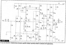
Randy Slone's book has a circuit or two that applies the Blameless principles, complete with PCB layouts.
Example from book below:
An externally hosted image should be here but it was not working when we last tested it.
Example from book below:
Attachments
Last edited:
- Status
- This old topic is closed. If you want to reopen this topic, contact a moderator using the "Report Post" button.
- Home
- Amplifiers
- Solid State
- Doug Self Circuits