Re: those transformers looking good with your great amp...
Hi, the transformer is a special order. Your Leach looks great too!

cyril_hk said:Hi Panson where do you get your transformers, seem likes some kind of low profile version. Looks really great!
Anyway, I just finished mine right early of May, no current limiter too, with all home made PCBs.
http://hk.geocities.com/cyrilwoo/
Cheers
Hi, the transformer is a special order. Your Leach looks great too!
Re: Re: those transformers looking good with your great amp...
This low-profile transformer was originally ordered for a low-profile chassis. But I eventually use regular chassis for installing a big (original) heat sink.
panson_hk said:
Hi, the transformer is a special order. Your Leach looks great too!
This low-profile transformer was originally ordered for a low-profile chassis. But I eventually use regular chassis for installing a big (original) heat sink.
hi, panson can you contact me please thru email? I cannot do the same...
Also , that missing 1W measurement would be very cool!! Another question, I found a pdf on www bout an lme49810 front end with Leach output stage, is that yours ? Im fairly sure its yours and Im extremely interested about that one !!
Also , that missing 1W measurement would be very cool!! Another question, I found a pdf on www bout an lme49810 front end with Leach output stage, is that yours ? Im fairly sure its yours and Im extremely interested about that one !!
tritosine said:hi, panson can you contact me please thru email? I cannot do the same...
Also , that missing 1W measurement would be very cool!! Another question, I found a pdf on www bout an lme49810 front end with Leach output stage, is that yours ? Im fairly sure its yours and Im extremely interested about that one !!
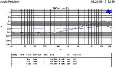
Here is 1W, 10W and 50W THD vs freq.
Yes, I this is my proposal. Thank you for your interest! I will post results of this project when available.
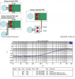
The amplifier (LEACH 150) has an on-board power supply (rectifier and reservoir cap 2200 uF x 8 per rail). I compared the THD of the amplifier for using its on-board supply to using a separate supply which has the same topology with 10000 uF per rail. Interestingly, THD at low freq region associated with the separate supply is better than its counterpart.
I also measured THD for using onboard PSU with an external transformer (same as internal). This helps us to make more meaningful comparison.
It can be seen that using a separate PSU achieves lower THD in low freq. region. It seems obvious the on-board PSU layout responsible to the degraded performance.
Attachments
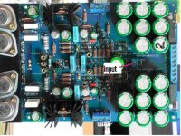
I continue my journey of the above distortion evaluation. The rising low frequency THD is probably due to on-board reservoir capacitors’ charge and re-charges current. The capacitors are located very close to input terminal. They share the same ground plane (top layer). The ground area between +V rail caps and –V rail caps are very noisy. Hence, the input ground is polluted.
Attachments
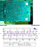
I measured the waveform between ground A and B. Non-zero PCB resistance given non-zero voltage between A and B when there is current flowing. Since input ground point is in the middle of the current path of A and B, input ground is polluted.
Waveform between point A and B, and distortion residual are shown. You can see the two signals are correlated to some extent.
PS: Distortion residual means remaining signal where the fundamental component is removed.
Waveform between point A and B, and distortion residual are shown. You can see the two signals are correlated to some extent.
PS: Distortion residual means remaining signal where the fundamental component is removed.
Attachments
I actually have a set of these same blue pcb's I got off ebay a couple of years ago. They came with dc servo boards also. At the time I bought it, it was advertised as a full kit. Once I received only the pcb's I checked the listing again and in small, ultra fine print at the bottom it said "pcb's only." I guess I should have looked everything over more carefully.
I never could find a parts list for the things. Diyzone doesn't seem to exist anymore. Anybody here have a parts list for this clone?
I never could find a parts list for the things. Diyzone doesn't seem to exist anymore. Anybody here have a parts list for this clone?
Hi. I need that part list too. Please!
here you go.
The BOM (bill of material) is translated with google...
I have the PCB still did not build it.
Attachments
- Status
- This old topic is closed. If you want to reopen this topic, contact a moderator using the "Report Post" button.
- Home
- Amplifiers
- Solid State
- My Leach Amp Clone (LEACH 150)