happyboy said:What i understand from the example is that i must use a feedback resistor that when matched with the input capacitance of the Opamp must be out of the unity gain bandwidth of the opamp? If what i understand is right, then how do i calculate what value of a resistor to use with different input capacitance of different opamp?
This is just an example of a possible problem - for many opamps there is no data available for the input capacitance. It is sensible in an audio opamp application to keep the value of a feedback resistor between 1K and 10K - most of the time you shouldn't have a problem. You need to be aware about potential stability issues if you try to use opamps designed for high frequency applications and not for audio.
Cheers
Alex
x-pro said:
This is just an example of a possible problem - for many opamps there is no data available for the input capacitance. It is sensible in an audio opamp application to keep the value of a feedback resistor between 1K and 10K - most of the time you shouldn't have a problem. You need to be aware about potential stability issues if you try to use opamps designed for high frequency applications and not for audio.
Cheers
Alex
Point noted there and i think i will use OPA2134 instead of AD826.
Here is the redrawn schematic. Hope its stable now.
Attachments
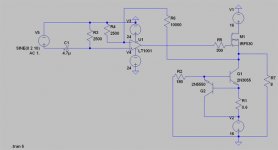
happyboy said:Here is the redrawn schematic.
Q2 is upside down. It may even work but rather badly
")
Cheers
Alex
x-pro said:
Q2 is upside down. It may even work but rather badly
Cheers
Alex
Yikes! No wonder there was alot of distortion if i biased that thing below 1.4A. Now i can bias it at 1.2A and still make it work properly.
Just a question. Is an input impedance of 150K normal and acceptable?
AndrewT said:Hi,
the input impedance of the circuit you last posted is 2k5.
But it is not an e24 resistor value.
2k5//10k=2k.
Hi, sorry for the misconception there, i changed that resistor to 150K but did not update it here. I was quite worried cause its quite high i suppose.
Erm sorry but may i know whats a e24 resistor value?
Thanks!
AndrewT said:Hi,
1% resistors usually come in 24values per decade. so increments after 2k0 are 2k2, 2k4, 2k7,3k0.
If you can find someone offering e96 values then you can fill in the gaps, but they often cost much more.
Oh now i get it. Thanks!
jerluwoo said:This will give you better way to adjust your current so you can remove the resistor out of the output.
Hi Jerluwoo,
Thanks for your help. Here is the schematic that i redrawn. Is using 2N3906 for the PNP transistors alright?
Thanks!
Attachments
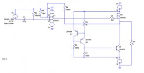
happyboy said:Here is the schematic that i redrawn.
I would strongly advise against this circuit. It would be thermally unstable in practice - almost as much as you original one. Stay with a proper two-transistor CCS as discussed earlier.
Cheers
Alex
x-pro said:
I would strongly advise against this circuit. It would be thermally unstable in practice - almost as much as you original one. Stay with a proper two-transistor CCS as discussed earlier.
Cheers
Alex
Hmm okay. But i would like to ask something, its not about being biased to each other but more of me wanting to know more. Why is that the biasing circuit proposed by Jerluwoo unstable?
happyboy said:Why is that the biasing circuit proposed by Jerluwoo unstable?
Because it relies on feeding a BJT with a constant base current. The collector current would be equal base current times the beta of the transistor. All would be fine in a simulator where the beta is a constant value. However in real life beta is strongly dependant on temperature, moreover it usually increases when transistor is heating up - so there is a positive feedback as increase in current would increase the power dissipation and the current of CCS would vary greatly. Worst still, the temperature of the device would vary with signal and so would current. On top of all this the dynamic output impedance of such CCS would be fairly low as the beta varies with collector voltage too.
These are the same reasons why I did advise you against your original CCS circuit - there was just a resistor to set the base current, however the resulting problems would be almost the same I've described.
Cheers
Alex
Hi,
The last circuit has two problems.
The 18r (R8) sets the constant current through the right hand side of the transistor pair. The current is 0.6V/18r=33.3mA.
Pass this current through the 1k0 (R1) lower leg load and you have 33.3V applied to the base emitter junction of the lower transistor. It does not work.
The opamp now has 1k9 on it's inverting input and 150k on it's non-inverting input.
The resulting output offset will cause asymetric clipping of high level signals and an increased level of distortion at higher signal levels well short of clipping.
AndrewT said:Hi,
The last circuit has two problems.
The 18r (R8) sets the constant current through the right hand side of the transistor pair. The current is 0.6V/18r=33.3mA.
Pass this current through the 1k0 (R1) lower leg load and you have 33.3V applied to the base emitter junction of the lower transistor. It does not work.
The opamp now has 1k9 on it's inverting input and 150k on it's non-inverting input.
The resulting output offset will cause asymetric clipping of high level signals and an increased level of distortion at higher signal levels well short of clipping.
Andrew,
I have to disagree
. In a first part the BE junction of the lower transistor is forward biased by this current, so it is OK, it will work but would be unstable with temperature etc. In a second part - happyboy has stated that he would use OPA2134 which has JFET inputs, very low input currents and would not produce any significant offset because of the resistor imbalance.Cheers
Alex
jerluwoo said:The wonderful thing about class a outputs is that once they reach full idle temperature they drift very little. I have used this method on countless little amp circuits and litterally tortured them without any problems.
The wonderful thing about electronics is that you can build better circuits by understanding how they work
. You can get away with many things - it doesn't mean you should.Cheers
Alex
AndrewT said:Hi,
could someone explain the operation of q1 when 33V appears across the BE junction.
These 33V would never appear there, so it's OK
. As the current from CCS would bias BE junction forward all you may get there is about 0.7V - unless there is no sufficient heatsink for this transistor and it eventually blows up... . Cheers
Alex
- Status
- This old topic is closed. If you want to reopen this topic, contact a moderator using the "Report Post" button.
- Home
- Amplifiers
- Solid State
- can someone help me check this circuit?