Hello,
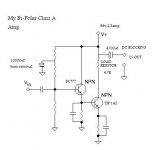
In 2000, I designed and assembled my first amp. Basicaly, I took a common class A transistor amplifier and scaled up the powersupply. I didn't have Internet access and most books talked of Class A theory, and went on to show Class B and AB with circuits. I don't have most of my drawings and math because I used bits of scrap paper and had to re-calc this and that to get what I needed. In the end I had assembled a single low power stage driving a power follower. With a supply of 36 volts at 2.5 amps, I put together a circuit that had a lot of Hum which I tamed with an extra resistor in series with the potential divider and took a 10,000uf cap to gnd. To block Hum on my output I used a 4700uf cap in series with the Loudspeaker, without it, the driver cone was pushed out to the end of its travel, in response to the DC on the output. OUCH
I used big 25watt resistors bolted to an old amplifier heatsink with the Follower transistors bolted to another heatsink. Both heatsinks were capable of handling the 20Wrms P/Ch of Class AB but not for a Class A, probably pushing a watt, I don't know.
When I put 2 together for stereo, I had a radio as sorce and 2 odd loudspeakers to listen with. I tell you, I could here more detail, than my main hifi. Queen's" Under Pressure", was played by a commecial station, and I could here sound I never heard before. I made the circuits safe, and took it from my little broom cupboard to the lounge, and wired in my CD player. WOW!
I had to listen in bursts of 10 minutes, because I was worried about over heating. I tried to cool it with a fan, but it was too noisy.
My partner and I both agreed it sounded way better than anything we'd listened to before. 2 weeks later and Thermal Runaway or similar, killed it. I was gutted.
In 2007, I want to do it again. And get right what I had done wrong.
Please can you give me some feedback. I think a lot of energy was wasted with the hum it suffered, I think the Hum contributed to the heat, let alone the fact its Class A anyway. The 10,000uf was an addition to the smoothers stacked on to the powersupply.
Also, I worry that if I build, say Rod Elliotts Mosfet Follower it won't sound as detailed, because he says his AB amp has less distortion, if I remember right. I was supprised to hear more detail, even through the Hum, which it suffered.
So please, give me your opinions. This circuit supprised me very much and although the circuit doesn't tell much, it was all I could find, my powersupply was poor as was my earth wiring. There was no star earth.Naughty.
Of the simplicity of the design, having only a few parts means I can spend more on better quality parts.
Cheers
Cup of coffee?
Attachments
Maybe it's just you have never heard a decent AB amp?
For a start power supply rejection is almost non-existent (as you have found with the hum problem) and it is woefully prominent in distortion when driving a speaker. Then again maybe that's what you perceived as 'detail'?
For a start power supply rejection is almost non-existent (as you have found with the hum problem) and it is woefully prominent in distortion when driving a speaker. Then again maybe that's what you perceived as 'detail'?
Hi,
Thought id chuck in my observations, im not an expert in electronics but your circuit diagram is a bit flawed.
Your using the power stage for gain, and the driver stage as a buffer, thought this would work better the other way round.
The 4700uf cap on o/p is connected straight to the PSU, connect it to the o/p transistors collector!
I think the 10000uf cap would be better placed on the supply rail then the whole circuit can benefit from it.
having so much resistance in the output current path is a bad idea too for a power amplifier as zout is Rc, and the emitter resistor will only reduce your voltage swing headroom, the stage is not really suited to power output.
In fact it all looks a bit dodgy to me, suprised it sounded ok .. the first decoupling cap isnt needed in a follower i dont think as it will only short out the emitter more at higher frequencies.
Im sure some other people can help more, probably correct me a bit lol..
Regards
Craig
Thought id chuck in my observations, im not an expert in electronics but your circuit diagram is a bit flawed.
Your using the power stage for gain, and the driver stage as a buffer, thought this would work better the other way round.
The 4700uf cap on o/p is connected straight to the PSU, connect it to the o/p transistors collector!
I think the 10000uf cap would be better placed on the supply rail then the whole circuit can benefit from it.
having so much resistance in the output current path is a bad idea too for a power amplifier as zout is Rc, and the emitter resistor will only reduce your voltage swing headroom, the stage is not really suited to power output.
In fact it all looks a bit dodgy to me, suprised it sounded ok
.. the first decoupling cap isnt needed in a follower i dont think as it will only short out the emitter more at higher frequencies.Im sure some other people can help more, probably correct me a bit lol..
Regards
Craig
Do not give up..continue into your research, those 2 stages, beeing simple sound nice
Reduce your current to a half of that, those transistors do not "really" dissipates 100 watts.....normally they hold 35 watts without problems.
You will succeed..... go ahead please.
Very good work...simple things uses to sound fine.
There are hundreds of forum folks that apreciate those minimalist designs.
Try to produce a separate sub circuit to bias this darlington one... than you will be able to produce a voltage amplifier using the first stage...no problems, you can couple with condenser and the sound will remain nice....diodes will provide you 1.2 volts (2 units) and them you will switch one your darlington and will control it..including the half of supply voltage into the colector.
The power will be small...1 amp and 18 volts into the colector.... 2 clean watts..... will play loud..do not worry, just use sensitive and soft speakers for that.
The first stage will need 5 volts and 2 miliamps., very small gain needed (colector resistance divided by emitter resistance)... easy to produce.... the input will be 750 milivolts to 2 volts maximum..so..you can calculate.
Good idea man...simple...will surprise many folks related sonics.
The current reduction will also help you related hum.
regards,
Carlos
Attachments
Thankyou for getting back to me....
destroyer X
Thanks for the confidence, I haven't dabbled with an iron for years.
Can you explain the diode thing? I used the potential divider in the original design, to bring about bias.
You wrote
you can couple with condenser and the sound will remain niceyou can couple with condenser and the sound will remain nice
Can you explain condenser, and why did you have a relay and variable resistor added to schematic?
Cup of coffee?
Getting back to it....
I'm reading about the Zen amplifier,
http://sound.westhost.com/project36.htm
The circuit seems loaded with components to a point I wouldn't say was minimalistic, and yet it has popularity. I havn't learnt much about the bias thing yet, but I can't help thinking I should just join the Pass club and make one already designed.
I see a large cost in power supply and heat sinking, and with wanting to use audio grade parts, the minimalistic approach seems to be sensible. Obviously without hearing one, I can't decide. Of course, we all want the best, the less the parts count , the more can be spent. Yes, I could also build an AB, as richieOOboy pointed out perhaps I've never heard a decent one. I've heard several top designs at the 1998 Hifi show in London, okay the acoustic surroundings were different to home, I wasn't blown away. The valve I heard glowing to Pink Floyd's Dark Side of the Moon, left an impact on everything else I heard. It was Class A. Okay it was a valve, if only I could remember its name!Doh, but surely a Single Ended transistor approach has got to sound good? Don't you think?
Cheers
Coffee anyone?
just built this, its simple and it sounds good
http://www.redcircuits.com/Page80.htm
http://www.redcircuits.com/Page80.htm
Attachments
Hello adason
Hi, So, tell me....whats it like? Just had a quick glance, it says response is 100 hz up, does that mean no low bass. What are you feeding it, and what loudspeakers are you using?
Circuit looks familiar to the Lindsay Hood, thats from memory which is vague.
Can you tell us more?
Cheers
Do you like coffee?
Hi Cup of coffee,
I love coffee. Mine is taken black.
Try a constant current source for your load. The output device can be a mosfet. What you want is right up Nelson Pass' alley. Drop into his forum here and have a read. You may need to parallel some devices to keep each in a linear range and also to spread the heat around.
-Chris
YES!!!Cup of coffee?
I love coffee. Mine is taken black.
Try a constant current source for your load. The output device can be a mosfet. What you want is right up Nelson Pass' alley. Drop into his forum here and have a read. You may need to parallel some devices to keep each in a linear range and also to spread the heat around.
-Chris
Hi Cup of Coffee,
About the link from your post no #5 :
http://sound.westhost.com/project36.htm
it talks about Zen amp only a little bit, then the author propose to make a "Death of Zen" amp, as for an article on the original Zen, by Mr. Nelson Pass , check this :
http://www.passdiy.com/
http://www.passdiy.com/legacy.htm
there are many variations on the Zen theme there.
Enjoy your coffee
Hartono
Dear Coffee... we already enjoy you in our cups
I hope you will enjoy our forum friends.
If you are new in this place...welcome!
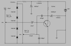
Do you like this one?
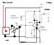
It is class A.... power into the darlington unit is around 30 watts...output power can go near 3 watts..... with 2.2 very clean watts.
The 12 ohms resistance will be really hot.... 20 watts is the minimum...you can use other values in series to reach those 12...of course you can make it a little different..
The input trimpot is to adjust you input audio not to saturate..it is a volume control...the other one, is the bias control, this is adjusted with the center tape with 180 ohms resistance to ground to start the adjustment.... adjust this one, the bias one, to obtain half the supply voltage into the darlington colector.
Be happy,
regards,
Carlos
I hope you will enjoy our forum friends.
If you are new in this place...welcome!
Do you like this one?
It is class A.... power into the darlington unit is around 30 watts...output power can go near 3 watts..... with 2.2 very clean watts.
The 12 ohms resistance will be really hot.... 20 watts is the minimum...you can use other values in series to reach those 12...of course you can make it a little different..
The input trimpot is to adjust you input audio not to saturate..it is a volume control...the other one, is the bias control, this is adjusted with the center tape with 180 ohms resistance to ground to start the adjustment.... adjust this one, the bias one, to obtain half the supply voltage into the darlington colector.
Be happy,
regards,
Carlos
Attachments
Here is the schematic.... it worked fine into the simulator
I suppose will produce nice sonics into real life.
A good and soft speakers...easy to be moved...not more than 5 watts unit will make a nice job if mounted inside a well tune enclosure.
This unit can reproduce 5 hertz without losses and goes to 20 kilohertz without significative problems shown in the simulator.
enjoy.
regards,
Carlos
Attachments
- Status
- This old topic is closed. If you want to reopen this topic, contact a moderator using the "Report Post" button.
- Home
- Amplifiers
- Solid State
- Where did I go wrong?