frickecello said:No, almost all channels work perfect with batteries and with the lab PSU, while others have some kind of low frequency noise (even when energized with batteries).
Then the ones that make noise must have a construction fault.
frickecello said:When I connect an unregulated power supply (cap-resistor-cap) to energize ANY channel a LOUD low frequency hum is heard sometimes the mic's signal is heard barely and sometimes just this hum.
That can happen if you haven't enough capacitance, the circuit is sensitive, or is not implemented correctly.
frickecello said:Yes it has got a lot of meters including those you mentioned, I dont know why but if I energize V- first, the current limiter switches on, this doesnt happen when I energize V+ first.
I wouldn't worry about it, it's due to the op-amp internal circuitry. I do wonder if you have damaged an op-amp by applying power in this way - you should apply both rails at the same time.
frickecello said:I've set the current limiter at 200 mA. since Im just energizing 2 dual op amp IC's at a time, 100 mA is the lowest setting for this nice piece of equipment.
Yes 200mA should be plenty for 4 op-amps.
frickecello said:I'm not very experienced designing pro power supplies and I dont know if this application needs it.
I do think you need a good regulated supply in this application. I have one on my website
") But I think you better solve your problems first before you try using my PSU and blame it on that
But I think you better solve your problems first before you try using my PSU and blame it on that NE5532 vs NJM4580
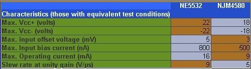
NE5532 is a NPN bipolar input op amp currently made by North American company Texas Instruments (original by Signetics).
NJM4580 is a PNP bipolar input op amp currently made by JRC (New Japan Radio) (check also Texas Instruments version RC4580)
This is the comparative between the two op amps based on the data sheet of each one... (Unfortunately specs are not given with the same test conditions or test conditions are not specified).
I will receive today some NJM4580's and RC4580's to compare them, according to my musical tastes and semi-trained ear (I play cello since I was 7 years old, however I dont have "golden ear").
I became interested in JRC chips because many medium cost-medium wattage amps I've repaired have them, I know they are really cheap and there are better op amps but JRC chips feature a great cost-performance ratio.
I will post the results soon.
Regards.
Marcelo Fricke Baptiste
ashok said:Is the NJM4580 the same as or as good as the NE5532 ?
NE5532 is a NPN bipolar input op amp currently made by North American company Texas Instruments (original by Signetics).
NJM4580 is a PNP bipolar input op amp currently made by JRC (New Japan Radio) (check also Texas Instruments version RC4580)
This is the comparative between the two op amps based on the data sheet of each one... (Unfortunately specs are not given with the same test conditions or test conditions are not specified).
I will receive today some NJM4580's and RC4580's to compare them, according to my musical tastes and semi-trained ear (I play cello since I was 7 years old, however I dont have "golden ear").
I became interested in JRC chips because many medium cost-medium wattage amps I've repaired have them, I know they are really cheap and there are better op amps but JRC chips feature a great cost-performance ratio.
I will post the results soon.
Regards.
Marcelo Fricke Baptiste
Attachments
richie00boy said:
Then the ones that make noise must have a construction fault.
That can happen if you haven't enough capacitance, the circuit is sensitive, or is not implemented correctly.
I wouldn't worry about it, it's due to the op-amp internal circuitry. I do wonder if you have damaged an op-amp by applying power in this way - you should apply both rails at the same time.
Yes 200mA should be plenty for 4 op-amps.
I do think you need a good regulated supply in this application. I have one on my website
Thanks for all those great observations, I will try your PSU for sure, can you post your website's link?
HELP: Remove hiss with isolation transformer?
I was testing the preamp with headphones (not connecting them directly to the preamp obviously, Im connecting the preamp to a pair of active speaker monitors that have headphone out) and I noticed that the preamp has a significant level of hiss, I want to use it to record practice sessions of a classical ensemble where I play and this level of hiss makes it useless.
I was thinking about removing or at least reducing it with an isolation 1:1 output transformer since the output is unbalanced, what do you think?
richie00boy said:An isolation transformer won't do anything for hiss, it's ground loop hum the fix.
Ok, thanks.
richie00boy said:
Also how do you know the hiss problem isn't the active monitors?
The active monitors are really quiet, I use them with other equipment too.
I am worried that maybe the pcb layout may be the problem since power supply decoupling caps share signal ground too.
How can I test one preamp channel for self-noise with an scope? (without adding microphone and cable picked up noise, just the circuitry noise)
In other words how can I know if this background hiss is normal or excessive?
Thanks for your help!
4580 is better than 5532 for audio use.ashok said:Is the NJM4580 the same as or as good as the NE5532 ?
The output stage (U4 and U5) is inherently unstable because there is a feedback loop enclosing two op-amps, thus producing 180º open loop phase shift at RF with no compensation to overcome this. You have to add a carefully chosen amount of "miller" compensation to each op-amp, enough to split the main global feedback loop in two smaller local loops at RF, but not enough to roll off frequency response at audio frequencies. It's a shame that everybody suggesting exotic $20 opamps hasn't noticed this. RF oscillation produces hiss and unexpected circuit behaviour as you described.
Good PCB layout, proper frequency compensation and component value choice are the main keys to low noise, then comes op-amp choice.
Use 5532 with low source impedances only (say below 1K) and to drive low impedance loads or audio transmission lines. Use LM833 for higher source impedances. Use TL072 or a better JFET op-amp for very high source impedances (like 10K or more) as it's actually less noisy than LM833 in these applications.
Remember to add some series R (say 100 ohms) to the output amplifiers if they are expected to drive audio transmission lines. This is a must to avoid cable capacitance from disturbing the op-amps at RF.
Hi,
are we still talking about post1 schematic?
u3 &2 have c9 &10 as feedback.
u4 is shown outside the balanced input loops, it looks like it is connected with positive feedback but an inverter feeding this node.
What is u5 doing, can't be a DC servo, no cap nor integrator.
are we still talking about post1 schematic?
u3 &2 have c9 &10 as feedback.
u4 is shown outside the balanced input loops, it looks like it is connected with positive feedback but an inverter feeding this node.
What is u5 doing, can't be a DC servo, no cap nor integrator.
Eva said:The output stage (U4 and U5) is inherently unstable because there is a feedback loop enclosing two op-amps, thus producing 180º open loop phase shift at RF with no compensation to overcome this. You have to add a carefully chosen amount of "miller" compensation to each op-amp, enough to split the main global feedback loop in two smaller local loops at RF, but not enough to roll off frequency response at audio frequencies. It's a shame that everybody suggesting exotic $20 opamps hasn't noticed this. RF oscillation produces hiss and unexpected circuit behaviour as you described.
Good PCB layout, proper frequency compensation and component value choice are the main keys to low noise, then comes op-amp choice.
Use 5532 with low source impedances only (say below 1K) and to drive low impedance loads or audio transmission lines. Use LM833 for higher source impedances. Use TL072 or a better JFET op-amp for very high source impedances (like 10K or more) as it's actually less noisy than LM833 in these applications.
Remember to add some series R (say 100 ohms) to the output amplifiers if they are expected to drive audio transmission lines. This is a must to avoid cable capacitance from disturbing the op-amps at RF.
Thanks, that is the kind of replies I wanted to read!
I was thinking about that too, I will add compensation as you suggest to see what happens.
I totally agree with you, if pro equipment features old op amps and still performs well, then it must be more important to carefully design PCB layout and circuit than to just buy space age op amps.
czbass said:
4580 is better than 5532 for audio use.
Which is the basis for that affirmation?
What microphones are you using or trying with this preamp?
Capacitor/condenser microphones need a special protection at the input.
Be careful with the capacitors you use at the input, as the quality may influence the audio quality. Use film types if you can.
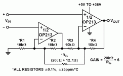
This is a very good mic preamp I built years ago. Uses a dual low-noise IC, in this case OP213 (which I don't think is made anymore) and you set the gain, with a pot or switch, between R2 and R3.
It should work fine with just one 5532. The 5532 is much better sounding than the LM833, but you can put a socket. Then try them and see which suits you better.
In any case put a blocking and protection combo as that used on the SSM2019, Figure 4.
http://www.analog.com/UploadedFiles/Data_Sheets/SSM2019.pdf
The next stage, which is no longer balanced, should have a small cap in the feedback, which could improve noise.
But remember one thing: you will have to build a pcb for this circuit, properly bypassed and regulated. If you don't you will have noise and oscillations.
Capacitor/condenser microphones need a special protection at the input.
Be careful with the capacitors you use at the input, as the quality may influence the audio quality. Use film types if you can.
This is a very good mic preamp I built years ago. Uses a dual low-noise IC, in this case OP213 (which I don't think is made anymore) and you set the gain, with a pot or switch, between R2 and R3.
It should work fine with just one 5532. The 5532 is much better sounding than the LM833, but you can put a socket. Then try them and see which suits you better.
In any case put a blocking and protection combo as that used on the SSM2019, Figure 4.
http://www.analog.com/UploadedFiles/Data_Sheets/SSM2019.pdf
The next stage, which is no longer balanced, should have a small cap in the feedback, which could improve noise.
But remember one thing: you will have to build a pcb for this circuit, properly bypassed and regulated. If you don't you will have noise and oscillations.
Attachments
- Status
- This old topic is closed. If you want to reopen this topic, contact a moderator using the "Report Post" button.
- Home
- Amplifiers
- Solid State
- NE5532 or LM833? For this balanced mic pre-amp