In his description of his cascode differential input stage at:
http://users.ece.gatech.edu/~mleach/lowtim/instage.html
Leach states:
"In addition to being part of the input low-pass filter, C1 improves the bandwidth of the feedback signal path through the diff amps for improved phase margin in the loop-gain transfer function."
I can't find any textbook or other such explanation of how this capacitor operates to extend the bandwidth of the feedback signal path through the diff amps, and how it improves the phase margin.
Can anyone give me an explanation of this, or point me to some helpful explanation? Thanks.
Long tail pair stage likes to be driven from relatively low source impedance at higher frequencies, because base-collector capacitance plays lesser role then, but this is not as much an issue when LTP is cascoded. If it really plays such a role here, I guess the effect is subtle.
Hmmm. Thanks. I was expecting something else. Do you have any info on how to predict the behavior due to various source impedance?
Pooge,
this question was asked a few months ago in another thread and the more experienced people were asked to comment (Bob Cordell, JC, some of the IC design folks et al).
If you run Spice simulations, you indeed do see a significant improvement in phase margin with an input filter.
I have my input filter pole set at 150Khz on my amp.
Without the filter, if you stick a square wave in with unrealistic rise/fall times (<<1uS) you can see ringing etc. with the filter of course, this is removed.
So, the reason I use it is to limit the input bandwidth so I dont get the ringing/overshoot. There will be those that will argue (correctly) that a normal music signal does not have very fast rise times, so why use a filter. I use it anyway (also good to kill RF and other out of audio band garbage).
If anyone can offer an explanation as to why the phase margin of the amp is actually improved, please let us know.
thank you
. . . . with the filter of course, this is removed . . .
Just to clarify, what I mean here is the output waveform no longer exhibits the ringing
Just to clarify, what I mean here is the output waveform no longer exhibits the ringing
Are you talking about this post?:
http://www.diyaudio.com/forums/showthread.php?postid=1226754#post1226754
http://www.diyaudio.com/forums/showthread.php?postid=1226754#post1226754
Bonsai said:Pooge,
this question was asked a few months ago in another thread and the more experienced people were asked to comment (Bob Cordell, JC, some of the IC design folks et al).
If you run Spice simulations, you indeed do see a significant improvement in phase margin with an input filter.
I have my input filter pole set at 150Khz on my amp.
Without the filter, if you stick a square wave in with unrealistic rise/fall times (<<1uS) you can see ringing etc. with the filter of course, this is removed.
So, the reason I use it is to limit the input bandwidth so I dont get the ringing/overshoot. There will be those that will argue (correctly) that a normal music signal does not have very fast rise times, so why use a filter. I use it anyway (also good to kill RF and other out of audio band garbage).
If anyone can offer an explanation as to why the phase margin of the amp is actually improved, please let us know.
thank you
Bonsai, not asking about the function of the cap as a part of an input filter for reducing bandwidth. I'm asking about its function of "improving" the bandwidth of the input differential.
Hi pooge
Often in power amps, the effects of low impedances are overlooked. People tend to think of a diff. input pair as being optimum but then feed them with moderate impedances (for example, on the feedback side perhaps a 10k feedback resistor is used with about 330 ohm feedback ratio resistor). You can see the effects of a 330 ohm versus 33 ohm resistor on the frequency response using a simulator. (Of course you can run this simulation without a complete amplifier; and if you use 33 ohms you'll need to change the feedback reistor as well)
Therefore keeping the input stage operating from a low input impedance (which is given by the shunt input capacitor) actually has the effect of increasing the bandwidth of the input stage because the impedance is low. Of course there is the loading effect on any series resistance, which acts to filter the upper frequency response if there is a resistor present. You can achieve similar results by using low input impedances (e.g. 50 ohms) but generally preamps aren't designed to drive such low impedances.
cheers
John
AndrewT said:search Graham Maynard.
He gave a good (understandable) explanation a week or so back.
Sorry, not that one.pooge said:Are you talking about this post?:
http://www.diyaudio.com/forums/showthread.php?postid=1226754#post1226754
It was about the two halves of the LTP operating in common emitter and common base mode. and both halves doing the same thing depending on whether the signal was entering from the inverting side or the non-inverting side.
When the signal comes in from the NFB loop to the inverting side, it forces the input transistor to operate in common base mode. To do this well the base should be tied to a good stable voltage reference (ground), the lower the source impedance the better that common base works. But he says it a lot better than I can manage.
Hi John,john_ellis said:Hi pooge
Often in power amps, the effects of low impedances are overlooked. People tend to think of a diff. input pair as being optimum but then feed them with moderate impedances (for example, on the feedback side perhaps a 10k feedback resistor is used with about 330 ohm feedback ratio resistor). You can see the effects of a 330 ohm versus 33 ohm resistor on the frequency response using a simulator. (Of course you can run this simulation without a complete amplifier; and if you use 33 ohms you'll need to change the feedback reistor as well)
Therefore keeping the input stage operating from a low input impedance (which is given by the shunt input capacitor) actually has the effect of increasing the bandwidth of the input stage because the impedance is low. Of course there is the loading effect on any series resistance, which acts to filter the upper frequency response if there is a resistor present. You can achieve similar results by using low input impedances (e.g. 50 ohms) but generally preamps aren't designed to drive such low impedances.
if the input grounding resistor were 20k, setting Zin to this value and the source impedance (with or without a DC blocking capacitor) were <=50ohms, would the source provide effective loading of the LTP? Then only low frequencies would present a high Rs when the reactance of the blocking cap takes on a bigger effect, but this still allows the majority of the audio spectrum and above to operate well.
john_ellis said:Hi pooge
Often in power amps, the effects of low impedances are overlooked. People tend to think of a diff. input pair as being optimum but then feed them with moderate impedances (for example, on the feedback side perhaps a 10k feedback resistor is used with about 330 ohm feedback ratio resistor). You can see the effects of a 330 ohm versus 33 ohm resistor on the frequency response using a simulator. (Of course you can run this simulation without a complete amplifier; and if you use 33 ohms you'll need to change the feedback reistor as well)
Therefore keeping the input stage operating from a low input impedance (which is given by the shunt input capacitor) actually has the effect of increasing the bandwidth of the input stage because the impedance is low. Of course there is the loading effect on any series resistance, which acts to filter the upper frequency response if there is a resistor present. You can achieve similar results by using low input impedances (e.g. 50 ohms) but generally preamps aren't designed to drive such low impedances.
Problem is that when you start going much lower than 330 ohms for the feedback resistor to ground, the DC coupling capacitor required (to prevent the LTP voltage offset being multiplied by the closed loop gain) becomes rather large; as does the current forced through it. This can be a problem if you are worried about capacitor distortion.
A better option woud be to cascode the LTP.
Cheers,
Glen
I was just considering that the situation might arise due to Miller effect, the Miller capacitance forming a LP filter with the source resistance? (If so, then a cascode input could reduce the Miller effect.)
A shunt capacitor at the input would bypass the input resistance as a source, lowering the source impedance at high frequencies. But this would shunt the input signal away from input, so I maybe this isn't the right thinking about improvement of differential bandwidth vs. input filtering.
A shunt capacitor at the input would bypass the input resistance as a source, lowering the source impedance at high frequencies. But this would shunt the input signal away from input, so I maybe this isn't the right thinking about improvement of differential bandwidth vs. input filtering.
Draw a small-signal diagram, and it should become apparent. Don't forget to include Cbe of the transistors. You may omit Cbc, though. That is probably not what matters here.
The input capacitor will form a capacitive voltage divider toghether with the Cbe's to help keeping up the voltage over the transistor b-e junctions at high frequencies.
The input capacitor will form a capacitive voltage divider toghether with the Cbe's to help keeping up the voltage over the transistor b-e junctions at high frequencies.
pooge said:I was just considering that the situation might arise due to Miller effect, the Miller capacitance forming a LP filter with the source resistance? (If so, then a cascode input could reduce the Miller effect.)
Miller capacitance is part of it; much more so if very low noise BJT's or JFETs are used for the LTP differential pair, as such devices typically have quite high collector-base and drain-gate capacitance.
spice is only as good as the models, but the principle seems to be easily seen in this sim
R1 is the source input R, easliy 10K for a 50K volume pot
R3 at 1K is more typical of feedback network R
V2 AC source shows the AC gain for the feedback signal through the diff pair to the input of the VAS ( at R2, V(out) )
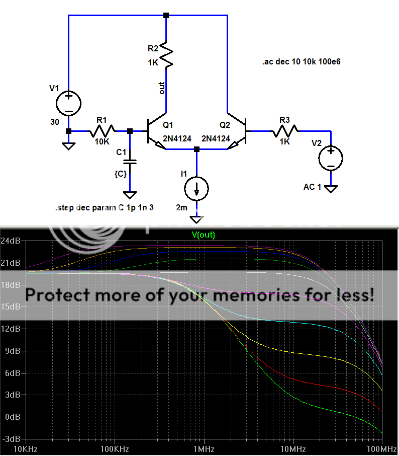
the optimum for these Q models seems to be ~46 pF (white)
~46 pF input gnd/bypass gives the flatest reponse with 48 degrees extra phase margin at 2.6 MHz
but the 2nd order slope gives more phase shift beyond 15 MHz for the peaked response vs the 1p "0" C1 trace (green)
R1 is the source input R, easliy 10K for a 50K volume pot
R3 at 1K is more typical of feedback network R
V2 AC source shows the AC gain for the feedback signal through the diff pair to the input of the VAS ( at R2, V(out) )
the optimum for these Q models seems to be ~46 pF (white)
~46 pF input gnd/bypass gives the flatest reponse with 48 degrees extra phase margin at 2.6 MHz
but the 2nd order slope gives more phase shift beyond 15 MHz for the peaked response vs the 1p "0" C1 trace (green)
Hi Andrew T
Using a 20k input resistor is not a problem if the preamp output impedance is low. As you say, the preamp impedance is important on the input side.
There is a way to trick the feedback side with low impedances while keeping the dc path at 10 or 20k too. Use parallel RC networks which keep the ac gain balanced but shift the impedances down with frequency.
For example if you have a 10k and 330 ohm feedback network a 1k resistor in series with a 1 nF capacitor in parallel with the 10k needs a 33 ohm in series with a 30.3 nF capacitor in parallel with the 330 ohm to maintain a flat frequency response. This will improve the diff amp bandwidth over the range 15.9 kHz-159 kHz.
The capacitor and resistor values need to be highly accurate to maintain performance: 5% tolerance or better is needed, which is the main problem.
Some amplifiers have had stability problems in the past because of this change in frequency response with loading. If your design needed a low impedance to be stable, if may have been fine when connected to a preamp but unstable if the preamp were unplugged!
Or the other way round.
cheers
John
Hi Glen
Some of my best designs have been completely D.C.
They sound very good and as they have no capacitors in the audio path at low frequencies, low impedances aren't a problem. I'm a little surprised that more fully D.C. designs aren't seen, although I agree that the offset voltage may be a little worse.
cheers
John
john_ellis said:Hi Glen
Some of my best designs have been completely D.C.
They sound very good and as they have no capacitors in the audio path at low frequencies, low impedances aren't a problem. I'm a little surprised that more fully D.C. designs aren't seen, although I agree that the offset voltage may be a little worse.
cheers
John
Hi John.
I agree that complete DC coupling in the feedback path is the best way to go. If your input devices are well matched, the offset voltage at the output can be kept small. However, they do have to be quite well matched (or trimmed). Suppose you have a closed loop gain of 30. An input offset voltage of only 33mV will result in 1V at the output.
33mV isn't a lot, and if you are using BJT's, input bias current needs to be taken into consideration also. Suppose you have an LTP with a tail current of 4mA and your BJT's have a beta of 200. This gives an input bias current of 10uA.
If the non-inverting input is returned to ground via a 10k resistor to give a reasonable input impedance, there will be a voltage of 100mV developed across the 10k input resistor. A 330 ohm resistor on the inverting side to ground will only drop 10uA*330R = 3.3mV, giving a differential offset voltage of ~97mV, just due to input bias currents alone - not taking into account Vbe/hfe variations or tollerances of emitter degeneration resistors (if used).
With a closed loop gain of 30, the output offset voltage will be approximately 3V.
Really tightly matched JFET's for the LTP or a DC servo can be a solution here, but they don't come without other issues also.
Cheers,
Glen
Hi John,john_ellis said:There is a way to trick the feedback side with low impedances while keeping the dc path at 10 or 20k too. Use parallel RC networks which keep the ac gain balanced but shift the impedances down with frequency.
For example if you have a 10k and 330 ohm feedback network a 1k resistor in series with a 1 nF capacitor in parallel with the 10k needs a 33 ohm in series with a 30.3 nF capacitor in parallel with the 330 ohm to maintain a flat frequency response. This will improve the diff amp bandwidth over the range 15.9 kHz-159 kHz.
The capacitor and resistor values need to be highly accurate to maintain performance: 5% tolerance or better is needed, which is the main problem.
Some amplifiers have had stability problems in the past because of this change in frequency response with loading. If your design needed a low impedance to be stable, if may have been fine when connected to a preamp but unstable if the preamp were unplugged!
Or the other way round.
your description of the parallel RC seems close to what my Sugden power amp has. It keeps blowing a rail fuse (when the wrong size was fitted) when the input RCA is disturbed and sends full rail voltage to the speaker terminal. I have been lucky to discover this when testing and never lost a driver. You have got me wondering now!
- Status
- Not open for further replies.
- Home
- Amplifiers
- Solid State
- Diff amp input cap for improved phase margin