HI Glen
I agree that it is not possible to use DC coupling without some form of adjustment.
In one bipolar design, I used a compensation transistor to adjust the input bias current and track this with temperature.
THe transistor used in this stage was matched to the input stage transistors (matched triplet).
Slightly easier to design was to use FETs. Again I use closely matched transistors but they still need some fine adjustment.
People have reported thermal oscillation cycles of a few minutes - which I have also observed using TO-92's even tightly coupled thermally. Most people would specify a single package pair now - but maybe two SOT devices stuck together would have much better coupling and faster thermal response... I'll have to give this a try. Not easy because one of the two will be upside down on the other, with its legs in the air...
The bipolar stage with compensation appeared to work better than the FET stage, but I don't have any measurements to report.
cheers
John
I used a complinentary differential diferential input circuit (so 2x NPN and 2 x PNP). I do use a coupling cap in the feedback ntwork (1000F 16V in paallell with 1uF Stacked foil). The offset as measued at the output is 3.7mV. The use of a complimentary pair does reduce offset substantially, and especially so if you use high gain small signal transistors (BC547/557 or 550/560). BTW, I run each side of the pair at 5mA. The overall amp gain is 25x , so if I DC coupled the f/back I would expect <100mV of offset. A simple pot arrangement to null offset (see Amplifier Guru's solution)is fine and drift is minimal, though I don't need to do his on account of the AC coupling.
How the hell did we get here from phase margin improvements arising from a cap on the input side of the diff amp input?
How the hell did we get here from phase margin improvements arising from a cap on the input side of the diff amp input?
Bonsai said:
How the hell did we get here from phase margin improvements arising from a cap on the input side of the diff amp input?
My sentiments, exactly. I still don't have a handle on the approach. Since I am not SPICE savvy, I'm still at a loss as to how to go about determining the proper capacitor value. It appears that it needs an optimized value.
Hi Don S,
-Chris
Only if all four are matched for beta. This also improves the sound quality. Not my favorite input setup. A single diff pair seems to sound better and you can inject a current into the base to eliminate the DC offset. You can also use an integrator for the same purpose (Duo Beta and other names).I am new, but if the input was 2 complimentary LTP's I think the DC offset would be greatly reduced. This would be in my thinking because the input bias currents would be close to equal and compliments.
-Chris
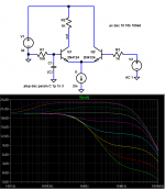
From my sim on the previous page I would say that while flat response may be somewhat intellectually attractive in this stage, the “overcompensated” response is quite usable, a few dB loop gain boost above 100 KHz could be welcome
So if you don’t want to measure for an optimum I would recommend just using the max C that gives a sufficiently high low pass corner with the input R, 100-200 KHz is necessary for the single pole response to not impact 20KHz frequency flatness
With very hot diff pair bias, and possibly cascodes it may be a good idea to make this input C a “Zobel” with a 10-100 Ohm in series with the C to add damping
Thanks. Your sims have two green traces. I assume the lowest green trace is the 1pf trace, and the traces rise with increasing "C". I also assume "overcompensated" means a "C" value greater than 46pf.
Would the 46pf "optimum" also be optimum with the hot bias or cascode scenario? In other words, is the damping recommended for all hot bias or cascodes, or just for a high "C" way above optimum used for LP filtering?
With very hot diff pair bias, and possibly cascodes it may be a good idea to make this input C a “Zobel” with a 10-100 Ohm in series with the C to add damping
Would the 46pf "optimum" also be optimum with the hot bias or cascode scenario? In other words, is the damping recommended for all hot bias or cascodes, or just for a high "C" way above optimum used for LP filtering?
 Or does the diff pair preform better with an input impedance dropping with frequency?
a diff pair can be limited in bandwidth by high source impedance, like volume pots in audio amps
an improvement to provide a low impedance at high frequencies with a C at the +in Q base, this increases the bandwidth of the diff pair for inverting input (feedback) signals which can improve loop stability
the bright green trace at the bottom is indeed the lo C, low bandwidth trace
when I cascode the "optimum" C drops ~1/2? - as the Miller multiplied Q1 Ccb is reduced, but the Q1 base still wants to be ac shorted to ground to maximize feedback input bandwidth
(same pic)
Attachments
Hi,
I had always thought these input components were a passive bandlimiting filter.
It appears that they indirectly impinge on the NFB loop by influencing the stage gain with respect to the return signal coming into the inverting input.
Does that mean these input components are inside the NFB loop? or are they outside the global FB loop?
If they are outside, then the overcompensated case would have some influence on how the high frequencies are reproduced. Is this an example of sibilance?
Hi Andrew T
Yes- many people putting designs together threw in a capacitor filter at the input to act as a slew-rate limiter, in essesnce, and as an RF filter.
Most people also forgot about the effect low impedances would have in boosting the bandwidth of the amplifier.
So it is true that although other threads have recommended dispensing with the input capacitor altogether, this cannot really be done if an amplifier is to allow for a range of input impedances.
You are right - and it is worth repeating that the stability of amplifiers has been dubious in the past because of added phase delays caused by differing impedances.
The input capacitor is outside the feedback loop but not disconnected from it. It causes a phase shift, and may create its own stability issues.
Don S- the main point to remember is that the bandwidth of an amplifier is dependent on the source and feedback loads. Keeping the input side at a low impedance helps; keeping the feedback side impedance low helps too, but these aren't "equal and opposite" effects, just "keep the impedance low both sides".
The best illustration is for a simple differential amplifier pair: with 10k impedance on each side the bandwidth may only be 100 kHz. With impedances less than 10 ohms, the bandwidth may be 10 MHz.
cheers
John
Hi Andrew T
I should have added after the above, that perhaps the addition of the capacitor keeps the input transistor operating with a high frequency response and usually helps with stability issues.
Whenever there is a feedback loop encompassing several stages, classically a stable system usually wants one dominantly slow stage (which is why some designers just seem to stick with a VAS - Miller capacitor) but keeping the operating speed of the input stage high helps with any feedback system by keeping the bandwidth high.
cheers
John
The input capacitor is outside the feedback loop but not disconnected from it. It causes a phase shift, and may create its own stability issues.
I should have added after the above, that perhaps the addition of the capacitor keeps the input transistor operating with a high frequency response and usually helps with stability issues.
Whenever there is a feedback loop encompassing several stages, classically a stable system usually wants one dominantly slow stage (which is why some designers just seem to stick with a VAS - Miller capacitor) but keeping the operating speed of the input stage high helps with any feedback system by keeping the bandwidth high.
cheers
John
Thanks John,
we make a grand team, you have the knowledge and I try to absorb it.
The overcompensated is assumed to roll off the treble earlier, but it appears the two outcomes partially cancel.
The two effects may leave a high Q remnant lurking to produce that HF grunge we can hear and could it also partly be the cause of the SSS sibilance?
we make a grand team, you have the knowledge and I try to absorb it.
so the rise in gain of the first stage could cause some HF overshoot.it is worth repeating that the stability of amplifiers has been dubious in the past because of added phase delays caused by differing impedances.The input capacitor is outside the feedback loop but not disconnected from it. It causes a phase shift, and may create its own stability issues.
The overcompensated is assumed to roll off the treble earlier, but it appears the two outcomes partially cancel.
The two effects may leave a high Q remnant lurking to produce that HF grunge we can hear and could it also partly be the cause of the SSS sibilance?
john_ellis said:Hi Andrew T
The best illustration is for a simple differential amplifier pair: with 10k impedance on each side the bandwidth may only be 100 kHz. With impedances less than 10 ohms, the bandwidth may be 10 MHz.
cheers
John
Are you talking about the stabilized close-loop bandwidth of the entire amp here?
A 46pf cap impedance is around 3500 ohms at 100kHz (neglecting series/parallel combination with other input resistors.)
pooge said:
Are you talking about the stabilized close-loop bandwidth of the entire amp here?
A 46pf cap impedance is around 3500 ohms at 100kHz (neglecting series/parallel combination with other input resistors.)
Correction: ~3500 @ 1MHz
It is ~35k @ 100kHz
We should also consider the effects here when a cascode is used. I noticed on my sims that even with a cascode the input cap made a big difference (I use 1k and 1nF for circa 150kHz pole). Correct me if I am wrong, but I assumed that with the cascode, the effects of the input source are greatly reduced - yet the input cap still makes a substantial difference in phase margin.
BTW, I also noted from my sims that a small cap (33pf) directly across the emitters of the input pair gave 8 degrees of additional phase margin (my degenration resistors are 150 Ohms).
BTW, I also noted from my sims that a small cap (33pf) directly across the emitters of the input pair gave 8 degrees of additional phase margin (my degenration resistors are 150 Ohms).
- Status
- This old topic is closed. If you want to reopen this topic, contact a moderator using the "Report Post" button.
- Home
- Amplifiers
- Solid State
- Diff amp input cap for improved phase margin