Hi!
I just finished my DoZ-preamp (ESP P37), and I want to adjust the bias, well, the as for the voltage at the collector of Q2/Q3: It is always somewhere between 32 and 32.7 V, no matter how many turns I set the trimpot to (it is a 22 turn trimpot), while it should be 15V. Turning the pot really does not seem to change anything, even if I wait more than 1 hour to let it adjust (is it correct that pin A of the pot is connected to ground?).
One thing I noticed: I could not get BC559 and BC549, but used C559C and BC549C, since I thought that makes no difference, am I wrong?
The stuffing / soldering seems to be OK, I actually build two modules (four channels), and both show the same characteristics...
I do not want to bother R. Elliot, so I first look here for help...
Any comments would be greatly appreciated.
Ciao,
Arndt
DoZ pre-amp
ESP Project 37 - Minimalistic Discrete Preamplifier
There are several good tweaks you can do on such
a simple Preamp, as DOZ-pre.
I do not like the very low Current in Q1, the Input transistor. Like 80uA ....
But it can not without some other problems
just be raised by lowering R6 10k.
Lowerering R6 means lowering R5 22k and R4 10k, as R5/R4 set the gain.
Lowering R4 means increasing C3 22uF, they set low freq rolloff.
Increase C3, and it is no longer possible to use Polypropylene, or Filmcaps.
-----------------------
So I would do this, to keep low value on C3 (and avoid Electrolytics).
I would lower R6, so set bias in input transistor to 0.5-2 mA.
To compensate, without changing R4-R5-C3,
I would put a Constant Current Source
from Positive Rail into Emitter of Q1.
I am sure it would give this preamp better prestanda.
/halo - has his own version of DOZ-pre - in his mind
Cradle22 said:Hi!I just finished my DoZ-preamp (ESP P37), and I want to adjust the bias, well, the as for the voltage at the collector of Q2/Q3: It is always somewhere between 32 and 32.7 V, no matter how many turns I set the trimpot to (it is a 22 turn trimpot), while it should be 15V. Turning the pot really does not seem to change anything, even if I wait more than 1 hour to let it adjust (is it correct that pin A of the pot is connected to ground?).
One thing I noticed: I could not get BC559 and BC549, but used C559C and BC549C, since I thought that makes no difference, am I wrong?
Ciao, Arndt
An externally hosted image should be here but it was not working when we last tested it.
ESP Project 37 - Minimalistic Discrete Preamplifier
There are several good tweaks you can do on such
a simple Preamp, as DOZ-pre.
I do not like the very low Current in Q1, the Input transistor. Like 80uA ....
But it can not without some other problems
just be raised by lowering R6 10k.
Lowerering R6 means lowering R5 22k and R4 10k, as R5/R4 set the gain.
Lowering R4 means increasing C3 22uF, they set low freq rolloff.
Increase C3, and it is no longer possible to use Polypropylene, or Filmcaps.
-----------------------
So I would do this, to keep low value on C3 (and avoid Electrolytics).
I would lower R6, so set bias in input transistor to 0.5-2 mA.
To compensate, without changing R4-R5-C3,
I would put a Constant Current Source
from Positive Rail into Emitter of Q1.
I am sure it would give this preamp better prestanda.
/halo - has his own version of DOZ-pre - in his mind
DOZ
Hi, Arndt
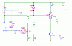
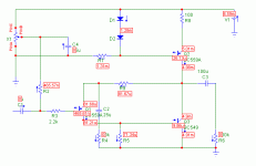
Did a quick sim on the schematic and give you the results. In the first pic you see the voltage points and on the second one the current flow. I didn't keep the part numbers from the original schema, but that will be no problem i think. The 100k trim pot is at 42%. At 100% i get 29.85V, at 50% 17.45V and at 0% 2.66V
The BC549C and BC559C can't be the problem i think, they have a higher Hfe basically.
/Hugo Hope this helps...a bit
Hi, Arndt
Did a quick sim on the schematic and give you the results. In the first pic you see the voltage points and on the second one the current flow. I didn't keep the part numbers from the original schema, but that will be no problem i think. The 100k trim pot is at 42%. At 100% i get 29.85V, at 50% 17.45V and at 0% 2.66V
The BC549C and BC559C can't be the problem i think, they have a higher Hfe basically.
/Hugo Hope this helps...a bit
Attachments
Re: DoZ pre-amp
Hi!
Your own version, would it be something like this:
?
Right now I do not want to change so much on the original layout, but I plan a preamp based on this OP discussed in a german forum (it is a kind of a ripoff of Thel's MusicAmp 2000) later on.
Well, thank you for simulating the schematic with spice (I just recently learned how to use eagle, Spice I have yet to try...), now I can check voltages across the whole circuit, and not just at the collector...
By the way, is a trimpot very easily destroyed by turning the screw some degrees too far? I noticed pressure increasing while turning the screw, but before I stopped, there was a faint "click" in the pot...
Well, thanks for your replies,
Arndt
Hi!
halojoy said:
There are several good tweaks you can do on such
a simple Preamp, as DOZ-pre.
I do not like the very low Current in Q1, the Input transistor. Like 80uA ....
But it can not without some other problems
just be raised by lowering R6 10k.
Lowerering R6 means lowering R5 22k and R4 10k, as R5/R4 set the gain.
Lowering R4 means increasing C3 22uF, they set low freq rolloff.
Increase C3, and it is no longer possible to use Polypropylene, or Filmcaps.
-----------------------
So I would do this, to keep low value on C3 (and avoid Electrolytics).
I would lower R6, so set bias in input transistor to 0.5-2 mA.
To compensate, without changing R4-R5-C3,
I would put a Constant Current Source
from Positive Rail into Emitter of Q1.
I am sure it would give this preamp better prestanda.
/halo - has his own version of DOZ-pre - in his mind
Your own version, would it be something like this:
An externally hosted image should be here but it was not working when we last tested it.
?
Right now I do not want to change so much on the original layout, but I plan a preamp based on this OP discussed in a german forum (it is a kind of a ripoff of Thel's MusicAmp 2000) later on.
Originally posted by NetList
Hi, Arndt
Did a quick sim on the schematic and give you the results. In the first pic you see the voltage points and on the second one the current flow. I didn't keep the part numbers from the original schema, but that will be no problem i think. The 100k trim pot is at 42%. At 100% i get 29.85V, at 50% 17.45V and at 0% 2.66V
The BC549C and BC559C can't be the problem i think, they have a higher Hfe basically.
/Hugo Hope this helps...a bit
Well, thank you for simulating the schematic with spice (I just recently learned how to use eagle, Spice I have yet to try...), now I can check voltages across the whole circuit, and not just at the collector...
By the way, is a trimpot very easily destroyed by turning the screw some degrees too far? I noticed pressure increasing while turning the screw, but before I stopped, there was a faint "click" in the pot...
Well, thanks for your replies,
Arndt
The "click" in the pot is normal. Reminds me of the old televisions where the tuning of the stations where done that way".
"and both show the same characteristics..."
You didn't swap transistor pins? BC549C and BC559C is EBC.
/Hugo still listening to a one channel ZenV4 - and happy
"and both show the same characteristics..."
You didn't swap transistor pins? BC549C and BC559C is EBC.
/Hugo still listening to a one channel ZenV4 - and happy
Netlist said:The "click" in the pot is normal. Reminds me of the old televisions where the tuning of the stations where done that way".
"and both show the same characteristics..."
You didn't swap transistor pins? BC549C and BC559C is EBC.
/Hugo still listening to a one channel ZenV4 - and happy
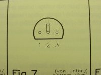
EBC, that means, if viewed from button:
......E
B
......C
or
......C
B
......E
?
/Hugo still listening to a one channel ZenV4 - and happy
/Cradle still sitting at work, not doing any work, but designing boards with EAGLE *G*
I'd rather be listening to my "modified 70s Marantz" and "End Millenium"....
Thanks,
Arndt
Cradle22 discrete OP
form 80uA to something like 500-2000uA.
--------------------------------------------------
Your OPamp project looks very Good.
I put it in my "music & schematics" website.
Hope you do not mind. If you change it, I will put the new version.
DiscreteOP-Cradle22.gif
--------------------------------------------------
About your problem.
It has to be at the input of Q1.
Trimpot-and the resistors to the B of input transistors.
Hope you have found the problem now.
At least Q2 doesn't work - have any current.
So the output goes high.
---------------------------------------------
If I build an OP-amp, it would be a normal 2-transistor input.
Not like yours, symetrical.
And it would probably not be better than "Cradle22-OP".")
/halo
No, what I said was that I have my ideas how to make DOZ pre a little better. Raise the Current in Input transistorTo compensate, without changing R4-R5-C3,
I would put a Constant Current Source
from Positive Rail into Emitter of Q1.
I am sure it would give this preamp better prestanda.
/halo - has his own version of DOZ-pre - in his mind
--------------------------------------------------------------------------------
Cradle22: -Your own version, would it be something like this:
form 80uA to something like 500-2000uA.
--------------------------------------------------
Your OPamp project looks very Good.
I put it in my "music & schematics" website.
Hope you do not mind. If you change it, I will put the new version.
DiscreteOP-Cradle22.gif
--------------------------------------------------
About your problem.
It has to be at the input of Q1.
Trimpot-and the resistors to the B of input transistors.
Hope you have found the problem now.
At least Q2 doesn't work - have any current.
So the output goes high.
---------------------------------------------
If I build an OP-amp, it would be a normal 2-transistor input.
Not like yours, symetrical.
And it would probably not be better than "Cradle22-OP".
/halo
Re: Cradle22 discrete OP
Hi!
I don't mind, although I have to mention that it is not "my" design, it was a combined effort of some people over at the German Audiomap forum, but they offered it as a "free" design, so it really is OK.
I tried building a board layout for it with eagle, and I want to couple the corresponding transistors (for heat coupling), but I am not really sure which ones to couple, right now I designed it with each transistor of the "upper part" facing the corresponding transistor of the "lower part", kind of if you simply mirror one half of the circuit... hope that's right, but since I really like to play around with eagle I can change it any time... and a completed module from thel (about the same as the above circuit) costs 65,- € (~ 70 US $)...
I will check my DoZ-Pre any time now, just came home... Hope it works...
Arndt
Hi!
halojoy said:
Your OPamp project looks very Good.
I put it in my "music & schematics" website.
Hope you do not mind. If you change it, I will put the new version.
DiscreteOP-Cradle22.gif
/halo
I don't mind, although I have to mention that it is not "my" design, it was a combined effort of some people over at the German Audiomap forum, but they offered it as a "free" design, so it really is OK.
I tried building a board layout for it with eagle, and I want to couple the corresponding transistors (for heat coupling), but I am not really sure which ones to couple, right now I designed it with each transistor of the "upper part" facing the corresponding transistor of the "lower part", kind of if you simply mirror one half of the circuit... hope that's right, but since I really like to play around with eagle I can change it any time... and a completed module from thel (about the same as the above circuit) costs 65,- € (~ 70 US $)...
I will check my DoZ-Pre any time now, just came home... Hope it works...
Arndt
Found the fault, me stupido...
Ahem...
Think before measuring...
Actually, there was some confusion about the pin-layout of the transistors... But not during soldering, but while measuring the current...
I measured at the base, not the collector like I should have. I thought that I tried every pin yesterday, but obviously I didn't...
Works alright, now I'm connecting all the stuff to volume pot and cinch connectors...
I have to say, that this should simply be an experiment, since I do not use preamps, I directly connect PC output to my amps, but who knows? And since DoZ itself comes next, maybe I will throw out some other equipment...
Thanks anyway for your help! I was really surprised to get so much help in such a short time... and it was good that I did not bother R. Elliot himself...
Ciao,
Arndt

If I build an OP-amp, it would be a normal 2-transistor input.
Not like yours, symetrical.
Can you expand a little bit on your motives why?
Symmetrical or non-symmetrical - Search my posts
I have explained this in another thred - use search
you might ask the makers of AD797
and other state-of-the-art OP-amps, the same question
basically I fínd it easier to find 2 closely matched NPN+NPN
than NPN+PNP. And seems I am not the only.
you can ask Nelson, why he doesn't use NPN+PNP MOSFETS
in his most famous amplifiers.
As long as they work fine, what is there to explain?
I have said before, that there is many roads to Roma.
And they all end up in Roma.
One design getting there, is not excluding other,
symmetrical approaches, to get there, too.
But that is just not my way of doing it.
/halo has good reasons - for doing things his way
edmedm said:Can you expand a little bit on your motives why?
I have explained this in another thred - use search
you might ask the makers of AD797
and other state-of-the-art OP-amps, the same question
basically I fínd it easier to find 2 closely matched NPN+NPN
than NPN+PNP. And seems I am not the only.
you can ask Nelson, why he doesn't use NPN+PNP MOSFETS
in his most famous amplifiers.
As long as they work fine, what is there to explain?
I have said before, that there is many roads to Roma.
And they all end up in Roma.
One design getting there, is not excluding other,
symmetrical approaches, to get there, too.
But that is just not my way of doing it.
/halo
has good reasons - for doing things his wayThe "click" in the pot is normal. Reminds me of the old televisions where the tuning of the stations where done that way".
"and both show the same characteristics..."
You didn't swap transistor pins? BC549C and BC559C is EBC.
/Hugo still listening to a one channel ZenV4 - and happy
I use BC 558C, and first time, I have similar problem. Later I realize that I misplace the EBC vs CBE of transistor pinout, but the old transistor was broken (replace with new one), then it works.
But now, I try to increase the voltage input to 60 V, assuming half of it is 30, max of transistor max VCE from datasheet (since it is connected to power amp), I got the same problem, pot does not affect the output voltage. I suspect the transistor is broken either due to voltage limitation, or due to wrong setup of bias (start position of pot) so that Vb become > Ve of Q1 by mistake.
Anyway, why there should be Q1, not just connect the input to basis of Q2, without 10k resistor from basis of Q2 to V- like simple pre amp with CCS? What is the purpose of Q1? Gain should be enough by Q2 itself, and feedback could be retrieved by connected basis to collector or to output of PoA.
Thanks,
Ervin L
- Status
- This old topic is closed. If you want to reopen this topic, contact a moderator using the "Report Post" button.
- Home
- Amplifiers
- Solid State
- Help on DoZ pre-amp