Hi ,
I just found a power amplifier project .
http://users.otenet.gr/~athsam/power_amp_300w.htm
Take a look !
I just found a power amplifier project .
http://users.otenet.gr/~athsam/power_amp_300w.htm
Take a look !
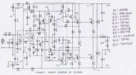
Power 300 Watt Amp
What is noticable
is that it uses Output Stage where
the Output is taken from the Collectors of the transistors.
So it uses some voltage amplification in the output stage.
Does not have to be bad.
I wonder what transistors are used.
In the input and the output?
------------------------------------------
here it is:
Q1-2-3= BC547
Q4-5-6= BC557
Q7-11-12= BD140 or BC640
Q8= BC549
Q9-10-15= BD139 or BC639
Q13-14= MJ15004
Q16-17= MJ15003
------------------------------------------
Very nice for us "homebuilders"
This is transistors that are very easy to find
in every part of the world.
Not often designers think of that.
If we use unusual and very new transistors, =exotic
it can be very difficult to replace, if something goes wrong.
Designs for DIYselvers should consider
how a potential builder can get the parts easy.
A common factor of Very Popular Successful amplifier-projects
is that they use semiconductors that belongs to "the mainstream"
of production, by the BIG manufacturers.
So this looks good to me.
But I will never need a 300 Watt Amplifier.
Never more then 50-100 Watt, in worst case.
/halo
What is noticable
is that it uses Output Stage where
the Output is taken from the Collectors of the transistors.
So it uses some voltage amplification in the output stage.
Does not have to be bad.
I wonder what transistors are used.
In the input and the output?
------------------------------------------
here it is:
Q1-2-3= BC547
Q4-5-6= BC557
Q7-11-12= BD140 or BC640
Q8= BC549
Q9-10-15= BD139 or BC639
Q13-14= MJ15004
Q16-17= MJ15003
------------------------------------------
Very nice
for us "homebuilders"This is transistors that are very easy to find
in every part of the world.
Not often designers think of that.
If we use unusual and very new transistors, =exotic
it can be very difficult to replace, if something goes wrong.
Designs for DIYselvers should consider
how a potential builder can get the parts easy.
A common factor of Very Popular Successful amplifier-projects
is that they use semiconductors that belongs to "the mainstream"
of production, by the BIG manufacturers.
So this looks good to me.
But I will never need a 300 Watt Amplifier.
Never more then 50-100 Watt, in worst case.
/halo
A great Collection of Pre&Power amps
A great Collection of Pre&Power amps
at the same site djdan
found this 300W.
-----------------------------------
High Power amplifier 170W in 8 ohms
Power Amplifier 60W Class A -in Greek
Power Amplifier 60W Class A -in English
Power Amplifier 40W Class A By Nelson Pass
Power Amplifier 60W / 8Ù Class AB
High Power amplifier 300W updated
HAFLER DH-200 - Power amplifier 100W with V-MOSFET
Power Amplifier 100W with V-MOSFET transistor [1]
Electrocompaniet - The 2 Channel Audio Power Amplifier
Power Amplifier with STK40xx series module IC
Small Power Amplifier 8W / 8Ù with TDA 2030
Power amplifier 12W with MOS FET transistor
Collection of little Bridge Power Amplifier
---------------------------------
just some samples from this page:
http://users.otenet.gr/~athsam/#Audio_Power
here is preamps:
http://users.otenet.gr/~athsam/#Audio_Preamplifier
---------------------------------
Moving Coil Head pre-preamlifier [1]
Hi-Fi RIAA Phono Preamplifier for moving magnet cartridge [1]
Hi-Fi RIAA Phono Preamplifier for moving magnet cartridge [2]
Surround Sound Decoder
Audio Preamplifier with Digital Volume
Stereo Preamplifier with elect. adjustment Volume-Balance-Treble-Bass
Variable High-Pass 20HZ to 200HZ Filter
----------------------------------
Very Nice Collection!
Sam Electronic Cicuits
----------------------------------
He also have a terrific Database - with DATAsheets - Regulators, IC & Transistors & some Tubes
http://users.otenet.gr/~athsam/database.htm
Fantastic!
/halo
A great Collection of Pre&Power amps
at the same site djdan
found this 300W.
-----------------------------------
High Power amplifier 170W in 8 ohms
Power Amplifier 60W Class A -in Greek
Power Amplifier 60W Class A -in English
Power Amplifier 40W Class A By Nelson Pass
Power Amplifier 60W / 8Ù Class AB
High Power amplifier 300W updated
HAFLER DH-200 - Power amplifier 100W with V-MOSFET
Power Amplifier 100W with V-MOSFET transistor [1]
Electrocompaniet - The 2 Channel Audio Power Amplifier
Power Amplifier with STK40xx series module IC
Small Power Amplifier 8W / 8Ù with TDA 2030
Power amplifier 12W with MOS FET transistor
Collection of little Bridge Power Amplifier
---------------------------------
just some samples from this page:
http://users.otenet.gr/~athsam/#Audio_Power
here is preamps:
http://users.otenet.gr/~athsam/#Audio_Preamplifier
---------------------------------
Moving Coil Head pre-preamlifier [1]
Hi-Fi RIAA Phono Preamplifier for moving magnet cartridge [1]
Hi-Fi RIAA Phono Preamplifier for moving magnet cartridge [2]
Surround Sound Decoder
Audio Preamplifier with Digital Volume
Stereo Preamplifier with elect. adjustment Volume-Balance-Treble-Bass
Variable High-Pass 20HZ to 200HZ Filter
----------------------------------
Very Nice Collection!
Sam Electronic Cicuits
----------------------------------
He also have a terrific Database - with DATAsheets - Regulators, IC & Transistors & some Tubes
http://users.otenet.gr/~athsam/database.htm
Fantastic! /halo
Yeah, Halojoy, using easily available components is indeed a good design-objective - especially for guys like me who live in a country called India. Only the 62V/5W zener (D2) seems bit of a problem to find, if at all. The circuit seems quite well designed and notably, symmetric.
The protection scheme uses both voltage & current sensing (R36 for emitter current & R37 for Vce), making it 'load-line' type of protection, which is definetely a step above the constant-current 'clipping' type of protection mechanism. The load-line cover helps exploit most of the SOA of the power devices, while still protecting them from breach of PD(max) due to a terribly reactive loading.
However, I find that only ONE of the two output transistors on each side is sensed. This would put a greater emphasis on matching, IMHO.
The BD139/140 at the driver stage gave me a bit of discomfort at first (as they are 80-volt devices), but then I saw the mid-point of R29/R30 grounded hard, so each of the devices is never likely to see more than one of the supply rails. This is possible because of the collector-coupled output topology.
One thing that I can't figure out is the R10 with a 'crossed' circle around it! Any explanations?
Please take a look at this one's power-supply schematic also: it uses a resistor in series with the transformer-primary to limit the surge current, which becomes quite a bit for such power levles! The resistor is shorted by a relay-contact after a delay.
Cheers
Would this be any good for powering my Peerless 850136s... they are 150watts RMS (I think) 8ohms This will give 200watts into 8ohms... perhaps its an overkill? perhaps 100watts will be enough? Only prob is I have very little money..... lol I think we've been through this before.. lol
lol I think we've been through this before.. lol1.If the amplifier have no more 2x500w/4ohm it work very well without the soft start .
The only problem may apear if it a large number number of amplifier will start in one moment ( sound reinforcement or P.A )
2. For home use a 300W amplifier will beat every high-end 60W amplifier. ( THD , Noise , Dynamics etc. ) . If you don't belive that , just make a test . Put a 60W amplifier on left speaker and 300W on the righ speaker and run both at 30W. After that try to give a 6dB bass or some loudness.
3. Conclusion ? Well , it may be interesting to know some opinions !
djdan
Now there is also a direct connection to Ground.
So you can use either option.
Start with direct ground.
Sometimes you can get "hum" or a ripple from 50Hz AC.
Then you can try the other option, with R10.
this is usuually a very low value,
like 10 ohms and below.
The ground connection and how/where you connect Ground
to the Chassis, is important in most power amps.
We do not want "ground-loops", so there should only
be one rail going to Central ground.
There are several good articles on the Web,
that gives advice about grounding considerations.
Regards
halo
You see that this R10 goes to ground.djdan:
One thing that I can't figure out is the R10 with a 'crossed' circle around it! Any explanations?
Now there is also a direct connection to Ground.
So you can use either option.
Start with direct ground.
Sometimes you can get "hum" or a ripple from 50Hz AC.
Then you can try the other option, with R10.
this is usuually a very low value,
like 10 ohms and below.
The ground connection and how/where you connect Ground
to the Chassis, is important in most power amps.
We do not want "ground-loops", so there should only
be one rail going to Central ground.
There are several good articles on the Web,
that gives advice about grounding considerations.
Regards
halo
johnthetweeker said:Has anyone built this amp?
hey man, we're all waiting for you to build one..
lol SkinnyBoy said:
hey man, we're all waiting for you to build one..
Ha, just trying to be "wise"... Heard someone say 'wise men learn from others' mistakes' !

300 Watt amp
I built this amp about 10 years ago,the original topic came from an Australian Magazine.It outputs 200 watts at 8 ohms and 300 watts at 4 ohms.The only problem about building this amp is finding the 62 Volt 5 watt zener.But you can easily replace it with an boosted zener.Use a regular 1 watt 62 volt zener and hook it up with a 20W transistor and your problem is solved.As for the sound quality I can say that it is above average.For PA use use a 50-0-50 AC 12A transformer and minimum 10,000uf/100V capacitor.The output section is good enough only for 8 ohm loads,for lower loads add additional pair of the MJ15003/15004.
I built this amp about 10 years ago,the original topic came from an Australian Magazine.It outputs 200 watts at 8 ohms and 300 watts at 4 ohms.The only problem about building this amp is finding the 62 Volt 5 watt zener.But you can easily replace it with an boosted zener.Use a regular 1 watt 62 volt zener and hook it up with a 20W transistor and your problem is solved.As for the sound quality I can say that it is above average.For PA use use a 50-0-50 AC 12A transformer and minimum 10,000uf/100V capacitor.The output section is good enough only for 8 ohm loads,for lower loads add additional pair of the MJ15003/15004.
Hey,
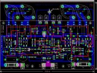
If you dug that amp, you may love this one. I have built 7 of these from kits and use them in my home theater setup.
Specs 300WRMS into 8 Ohms! +/- 75V rails @ 8A
Measured 242WRMS into 8 Ohms resistive w/sinewave input
368WRMS into 4 Ohms resistive w/ sinewave input
I think, with a bit better capacity of power supply, I'd get 300W into 8 Ohms.
Chris
Attachments
- Home
- Amplifiers
- Solid State
- 310W Power Amplifier