.
Hello friends,")
and all those others ( those so soon, so eager to anything others do )
You know, I have so many ideas.
And not enough many spice models to try them out optimallicy (with 'best' devices).
I wish I had 3-4 clever young comrades, with an open mind
and willing to set up and explore all new ideas.
And that I had the money to pay such 'my helpers'.
So here I am, with my limited time to spare .. in fact true for every man and woman ...
Not many will live to celebrate 200th birthday ....
---------------------------
Experimenting with Voltage Amplification Stage.
There are many ideas about input & ouput transistors.
They are important too.
But to have a good and not to un-linear VAS stage .. is a real blessing.
At least when every other stages are trimmed to last decimal.
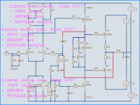
As you can see from attachment
this experimental setup use IRF TO-220 HEXFET for voltage amplification.
At a comparatively High Current.
My first version here, which shows good performance
uses JFET 2SK170 for input and TO-3 MJ15024 / MJ15025 ( hello JohnCurl !!!!! ) for output.
Not much more to say really.
If you know how to read a perfectly drawn schematic
you will get the idea and how it works without too much difficulty
Finally, this is according to my ideas.
How I have got the strength of diffrent transistor technologies:
1. JFETs are good for input. One quality is High Input impedance and low bias current.
2. MOSFETs are are good voltage amplifiers, they are fast!
3. BIG BIPOLAR working as Voltage Followers have low losses.
Even if noe are very good Output FETs that are just as good and probably will be the future ahead.
Enjoy my screen capture directly from my Sim Working Bench.
I will explore this idea further, when I have had some sleep and feel fresh again.
Audio Regards
lineup Contributing again ... with some own idea .. and design
Hello friends,
and all those others ( those so soon, so eager to
anything others do )You know, I have so many ideas.
And not enough many spice models to try them out optimallicy (with 'best' devices).
I wish I had 3-4 clever young comrades, with an open mind
and willing to set up and explore all new ideas.
And that I had the money to pay such 'my helpers'.
So here I am, with my limited time to spare .. in fact true for every man and woman ...
Not many will live to celebrate 200th birthday ....
---------------------------
Experimenting with Voltage Amplification Stage.
There are many ideas about input & ouput transistors.
They are important too.
But to have a good and not to un-linear VAS stage .. is a real blessing.
At least when every other stages are trimmed to last decimal.
As you can see from attachment
this experimental setup use IRF TO-220 HEXFET for voltage amplification.
At a comparatively High Current.
My first version here, which shows good performance
uses JFET 2SK170 for input and TO-3 MJ15024 / MJ15025 ( hello JohnCurl !!!!! ) for output.
Not much more to say really.
If you know how to read a perfectly drawn schematic
you will get the idea and how it works without too much difficulty
Finally, this is according to my ideas.
How I have got the strength of diffrent transistor technologies:
1. JFETs are good for input. One quality is High Input impedance and low bias current.
2. MOSFETs are are good voltage amplifiers, they are fast!
3. BIG BIPOLAR working as Voltage Followers have low losses.
Even if noe are very good Output FETs that are just as good and probably will be the future ahead.
Enjoy my screen capture directly from my Sim Working Bench.
I will explore this idea further, when I have had some sleep and feel fresh again.
Audio Regards
lineup
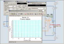
Contributing again ... with some own idea .. and designAttachments
2 Watt RMS, 4 Ohm fourier and THD analys
.
if you look at my attachment
you see good test results
For an unfair comparison:
I have not been able to get any lower Sim at 1 Volt RMS output
than 2.2 % THD into 10 kOhm. ( ~ 60 dB worse than my attachment into 4 Ohm)
I refer to the original Nelson single transistor 2SK170BL JFET Boz circuit.
(When optimise the drain resistor, (4k7) I could get this down to close 1% THD.
But not any lower.)
It should be clearly noted here
Nelson have never claimed JFET Boz to be a low distortion and HIFI preamplifier.
But instead JFET Boz is an easy very nice project for DIY builders,
that may sound ever so good as any other preamp!
Sound ever so good ...... hmmm, how come?
It has to do with 'tube sound' and let me quote
anorher magnificent audio thinker / constructor
Rod 'ESP' Elliot:
Regards, in the love of Audio Amplifiers
lineup
.
if you look at my attachment
you see good test results
For an unfair comparison:
I have not been able to get any lower Sim at 1 Volt RMS output
than 2.2 % THD into 10 kOhm. ( ~ 60 dB worse than my attachment into 4 Ohm)
I refer to the original Nelson single transistor 2SK170BL JFET Boz circuit.
(When optimise the drain resistor, (4k7) I could get this down to close 1% THD.
But not any lower.)
It should be clearly noted here
Nelson have never claimed JFET Boz to be a low distortion and HIFI preamplifier.
But instead JFET Boz is an easy very nice project for DIY builders,
that may sound ever so good as any other preamp!
Sound ever so good ...... hmmm, how come?
It has to do with 'tube sound' and let me quote
anorher magnificent audio thinker / constructor
Rod 'ESP' Elliot:
Conclusions
From everything that has gone on during development, I feel that my anti-MOSFET stance is justified for a Class-A design, at least, and that the concept of such an ultra simple amplifier is flawed if low distortion is the ultimate goal.
Certainly, some degree of low order harmonic distortion is not unpleasant, and may even add some degree of musicality to an otherwise "clinical" sound,
but the cost (i.e. loss of definition of complex passages, etc) is too high for my liking.
Even the bipolar transistor version is unacceptable in the most basic configuration, since although the distortion is lower, it is still too high - this does not qualify as hi-fi by any definition. The addition of global negative feedback (as shown in Figure 3) is the ONLY way to reduce the distortion to within acceptable limits.
http://sound.westhost.com/project36.htm
Regards, in the love of Audio Amplifiers
lineup
Attachments
VAS Volt Stage Hybride - Version 2a
Update.
---------------------------------------------
My Experiments with this new amplifier idea continues.
Version 2a of this hybride amplifier gives even more promising test data.
You can download schematic from my Diy Audio website.
I have used a new javascript for this download page.
This script, a mixture of PHP and JAVA, performs 2 functions:
- Detects what Browser visitor has. And if is old/new browser version.
- Can make a simple protection against un-limited downloads of stuff you have copyright of.
Here is download link, to this Experiment Amplifier:
Lineup new 'Hybride Amp', Version 2a ( 2007-06-18 )
Download
I had a few problems with this javascript, initially.
Hope it works.
Regards lineup
lineup said:
Hello friends,
Experimenting with Voltage Amplification Stage.
There are many ideas about input & ouput transistors.
They are important too.
But to have a good and not to un-linear VAS stage .. is a real blessing.
At least when every other stages are trimmed to last decimal.
As you can see from attachment
this experimental setup use IRF TO-220 HEXFET for voltage amplification.
At a comparatively High Current.
My first version here, which shows good performance
lineup
Update.
---------------------------------------------
My Experiments with this new amplifier idea continues.
Version 2a of this hybride amplifier gives even more promising test data.
You can download schematic from my Diy Audio website.
I have used a new javascript for this download page.
This script, a mixture of PHP and JAVA, performs 2 functions:
- Detects what Browser visitor has. And if is old/new browser version.
- Can make a simple protection against un-limited downloads of stuff you have copyright of.
Here is download link, to this Experiment Amplifier:
Lineup new 'Hybride Amp', Version 2a ( 2007-06-18 )
Download
I had a few problems with this javascript, initially.
Hope it works.
Regards
lineupI was about to put some comments on your schematic as post #1, as I have tried something similar in the past (no FET input though). But I came to your post #3 and you annoyed me. What is the purpose of such a stupid webpage?
If you want good feedback don't do stupid things like that. All you need to do is attach a PNG or PDF of the schematic. You aren't doing youself any favours. And I like to think I was a 'supporter' of yours up to now.
If you want good feedback don't do stupid things like that. All you need to do is attach a PNG or PDF of the schematic. You aren't doing youself any favours. And I like to think I was a 'supporter' of yours up to now.
Re: VAS Volt Stage Hybride - Version 2a
wow nice link!
??? oh man...
lineup said:
Here is download link, to this Experiment Amplifier:
Lineup new 'Hybride Amp', Version 2a ( 2007-06-18 )
Download
Regards
wow nice link!
1. JFETs are good for input. One quality is High Input impedance and low bias current. 2. MOSFETs are are good voltage amplifiers, they are fast! 3. BIG BIPOLAR working as Voltage Followers have low losses.
??? oh man...
Lineup , if you put up this Web page : http://lineup.awardspace.com/hybride_schema.php
it's in VERY bad taste. You wasted my time and bandwidth . Both are precious to me and obviously not to you.
So unless your page was hacked to appear as it does now with those childish blurbs , you better not give URL's for such pages on this forum. You might just drive away everyone from looking at your pages.
You just dropped your rating for no good reason !
Haha I think its funny that Lineup is just messing with everyone with that page. I think that using a mosfet for voltage amp is a good idea but the difficulty is the amount of current need to keep it linear inside the circuit. Did some playing using my simple class a as a testing circuit. Simmed distortion results were basically identical to that of a bipolar in the same posistion. The largest difference being the large amount of current used to put it in its linear range.
Attachments
Hi
Just a thought, wouldn't there need to be a 'degeneration' source resistor for U9 to set the current relative to the steady gate voltage from the regulator? I thought for vertical fets, Vgs decreases with increase in temperature, for this current level. I would guess that the output bias would began to increase as the circuit is left on since it's input bias is the VAS current, which would increase with temp, at least that is what the temp-co is telling me.
Just a thought, wouldn't there need to be a 'degeneration' source resistor for U9 to set the current relative to the steady gate voltage from the regulator? I thought for vertical fets, Vgs decreases with increase in temperature, for this current level. I would guess that the output bias would began to increase as the circuit is left on since it's input bias is the VAS current, which would increase with temp, at least that is what the temp-co is telling me.
jerluwoo said:
Simmed distortion results were basically identical to that of a bipolar in the same posistion.
The largest difference being the large amount of current used to put it in its linear range.
This is good info.
We may not gain by using HEXFET for VAS
in sll parameters, compared to BD139 etc etc.
But, as you noticed,
the VAS CURRENT Output = The Energy to drive FINAL Stage
is at very high comparative level.
The cure for capacitance is .....
... that's right ..... it is Ampere.
Regards
lineuplineup said:The cure for capacitance is .....
... that's right ..... it is Ampere.
...FAST ampere... which is why a cascode is worth an experimental representation here....IMO. I personally don't use an input stage capable of amperes.

In a conventional 3 stage circuit using the 'amplified diode' bias for the output, a lot of the increase in current would be offset by the thermal tracking action of the transistor mounted on the heatsink, at least I would think so. With that much current available from the vas, drivers before the output would not be needed. This could also be delt with by simply adding a temprature sensing resistor that increased resistance with temp into the vas current source. Many ways that it could be made to work correctly without having to get too complicated.
Hi
Assuming the VAS current increases with temperature with no degeneration on U9, if the output temperature is constant, the conductivity of the Vbe multiplier will be constant, since it is dependent on the output temperature, so output bias would increase. This may increase temperature of the outputs, increasing the conductivity of the Vbe multiplier, and keeping the circuit out of thermal run-away. Fine and dandy, but this makes the output bias not only dependent on output temperature, but also VAS CCS temperature as well. There may be no consequence in this case, but not all circuits are the same. If bias is set, and later the circuit is cold(off) and switched back on, there may be low bias or cross-over distortion until the transistors heat up. However, I see no consequence of using some degeneration feedback here. Adding a simple resistor would not complicate things.
Assuming the VAS current increases with temperature with no degeneration on U9, if the output temperature is constant, the conductivity of the Vbe multiplier will be constant, since it is dependent on the output temperature, so output bias would increase. This may increase temperature of the outputs, increasing the conductivity of the Vbe multiplier, and keeping the circuit out of thermal run-away. Fine and dandy, but this makes the output bias not only dependent on output temperature, but also VAS CCS temperature as well. There may be no consequence in this case, but not all circuits are the same. If bias is set, and later the circuit is cold(off) and switched back on, there may be low bias or cross-over distortion until the transistors heat up. However, I see no consequence of using some degeneration feedback here. Adding a simple resistor would not complicate things.
- Status
- This old topic is closed. If you want to reopen this topic, contact a moderator using the "Report Post" button.
- Home
- Amplifiers
- Solid State
- Experimenting ... Volt Stage Hybridically