Line amps
Sorry to take so long to reply. I did not realize that this post had progressed.
I think you are on the right track with those mods, if you have observed any signs of instability, I.e. overshoot on square wave signals, etc. Even very small instability has enormously detrimental effects on amplifier sound.
I am surprised that there was instability, but one of the things that makes publishing designs for the DIY area difficult, is that the designer has no control over the type and quality of components used. Your mods would make the line stage a little more robust with respect to component variations.
I like the differential VAS. Roughly a year after developing the 6000 I designed a fully symmetric MOSFET 200w power amp which uses a fully symmetric differential VAS. I have used this amp as my personal reference ever since, and over the years have compared it to a large number of high - end commercial power amps. I think it beats most of them for overall sound quality, although there have been a few power amps which may have been superior in some facets. I think part of the reason is the symmetric differential VAS, which provides large voltage gains with low open-loop distortion.
I have not seen Doug Self's comments that you refer to... do you have any references I could look up?
Dave
Hi David,
Deliighted to see you on here. I'm another fan (probably of Suzy's generation) that grew up lusting after your amp designs. To this day I still think the 6000 is my favourite power amp and I too have some Renesas (Hitachi) 162/1058s stashed away and have been planning to do my own 6000 PCB layout as, while Suzy's version looks wonderful, I wanted to stick with the higher power and through-hole components. I must confess to really liking the sound of the 5000 too, though not as much...
The reason I'm writing is I still have the line stage of your UF 6000 preamp. I never really thought it was as good as the power amp, and not long ago I decided to see if I could work out why. I believe it is perhaps not as stable as it should be as it shows quite pronounced ringing on square waves. I found this both in simulation and measuring the actual preamp with a 'scope. I also discovered a track missing in one channel of the original PCB, which probably didn't help...
Anyway, I played around in spice with different forms of compensation and found the the best looking result by ditching the input compensation (1n8 + R) and instead slugging the next differential stage with a 68pF cap across C-B of each transistor of the diff pair. This seemed to tidy things up nicely in the real circuit, with no visible signs of overshoot or ringing on square waves.
Unfortunately this was very much trial and error on my part, I don't have the necessary skills and knowledge to really know if this method of compensation is optimum, but it does seem to sound quite a lot better now. I'd be stoked if you could have a quick look at my mods and see if you think this is really a good idea. I don't have the means to measure distortion, but it certianly looks very low in simulation. I've attached the simulation screen grabs and can of course send the files if you're interested. The waveforms look identical on the 'scope. Please don't feel in any way obliged though, you've probably got much better things to be doing.
Do you think it's still a topolgy worth playing with? Douglas Self and others seemed to have dismissed the differential VAS as flawed in their publications. I'm curious to know whether the FET preamp you mentioned is based around that sort of discrete opamp toplogy?
Cheers, and also many thanks for the inspiration,
owdeo
Sorry to take so long to reply. I did not realize that this post had progressed.
I think you are on the right track with those mods, if you have observed any signs of instability, I.e. overshoot on square wave signals, etc. Even very small instability has enormously detrimental effects on amplifier sound.
I am surprised that there was instability, but one of the things that makes publishing designs for the DIY area difficult, is that the designer has no control over the type and quality of components used. Your mods would make the line stage a little more robust with respect to component variations.
I like the differential VAS. Roughly a year after developing the 6000 I designed a fully symmetric MOSFET 200w power amp which uses a fully symmetric differential VAS. I have used this amp as my personal reference ever since, and over the years have compared it to a large number of high - end commercial power amps. I think it beats most of them for overall sound quality, although there have been a few power amps which may have been superior in some facets. I think part of the reason is the symmetric differential VAS, which provides large voltage gains with low open-loop distortion.
I have not seen Doug Self's comments that you refer to... do you have any references I could look up?
Dave
Hi Dave,
No worries, great to hear from you and thanks for having a look. I've played around with it some more since and have increased the input stage currents by a factor of 4 while keeping the degeneration constant (ie increasing emitter Rs in the LTP). I figured this would improve the noise figure as I'm using a lower impedance volume pot and no balance pot in front of it. I also replaced the small film coupling cap at the input with a 22uF bipolar electro. These two changes have further transformed the sound quality and it's now the best preamp I've built and sounds far better than anything else I can compare it to. The midrange has snapped into focus and the sound is transparent and musically involving. I'll post the updated schematic if anyone's interested.
Regarding your updated design following the 6000, would you care to share any more details? The 6000 had a fully symmetrical differential VAS too didn't it? Reason I ask is I still intend to redesign the 6000 PCB so I can build it up - I already have all the parts ready. But if your later design is an improvement I'd rather spend the time on that, though of course only if you feel inclined to put it out there (or perhaps publish it in Silicon Chip? You never know, they might!).
Self's dismissal of balanced VAS stages was originally published in Electronics World in the early 90's in his series on amplifier distortion and is included in his Audio Power Amplifier Design Handbook - I have the 4th edition and it's in Chapter 4 under "The Balanced VAS". There's not much to read really, his summary is "...all seem to be open to the objection that the vital balance of the input pair is not guaranteed, and that the current through the bias generator is not well defined." These comments may make more sense if you consider that his work focuses almost exclusively on the Lin topology as though it is the only way to design a good amplifier.
Cheers
Owdeo
Hi guys and girls
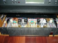
I managed to acquire an original mint condition series 5000 (eti477) power amp. in remarkable condition. Was being used regularly and performing very well.
A quick look over before connecting speakers and noticed DC voltage on the speaker terminals. About 80mV on each (in the negative)
I ran my meter over the powered up circuit and all voltages measured pretty well spot on with the voltages noted on the schematic.
There were two different sorts of BC550 (different manufacturers) on each board, so I replaced all 3 on each board with new ones that I had and matched them to withing 2 hfe of each other ( hfe = 430 )
This brought the offset voltage down to about 50mV on each channel.
Ok but not great.
Warming Q1 up wit
h my finger sees the voltage drop down.
Warming Q2 up sees the voltage rise.
These two transistors are too far apart to thermally bond them for stability.
Is it possible that the BF's could be causing this ?
Any advice from the gurus here ?
You really need to match for Vbe at the operating current, not hfe, as Vbe differences are multiplied by the amplifier gain.
I'd be swapping out the big electro on the feedback path, as any leakage there can cause grief, and it's not a new amp.
After that, brute force it with a trimmer between the input difamp emitter resistors, as is done on the AEM6000.
Lots of people chuck a big zener (18V from memory) between the collectors of the transistors opposite the fet gate drivers (Q7 and the one below it, but from the schematic I can see I can't read it's number) to balance out the dissipation inthat stage. That'd probably help to reduce DC offsets.
Thanks for the speedy reply suzyj.
"I'd be swapping out the big electro on the feedback path"
If this is C5 (100uF/25V) ? I did replace this cap on both modules and it made no difference to the offset voltage at all. I also tested the old ones that I removed and they both test perfect.
I monitored the offset voltage on the speaker terminals as I adjusted the quiescent bias. There was no change in the output offset voltage.
I'll go thru some BC550's and try to match some for Vbe instead of hfe and see what happens. To what degree do they need to be matched ?
I'll also pickup a couple of 18V zeners and see if that helps.
Failing that, I will try the brute force trimmer option as you suggested.
It concerns me that Q1 and Q2 (dif amp) are too far apart to be thermally bonded for stability, as just the heat from my finger on Q1 was enough to drift the voltage by about 10mV but i'll have to re-read Mr Tilbrooks original article on the 477 as I seem to recall that there was some design magic that did not require the input diff pair to be matched ?
Also, I noticed that one of the 100 ohm gate drive resistors looks like it has been a bit hot.
I have no idea what to make of this, any idea ?
Attachments
Quick update for those following along.
Discovered that if I short out R10 ( the 270 ohm Q1 emitter resistor) the output offset voltage decreases to 12mV !
Obviously I cannot just delete R10 ! so an actual proper solution is still needed.
Tried replacing Q1 and Q2 with Vbe match ( and pretty close hfe) transistors.
Made no difference.
Swapped Q1 and Q2 around, still no difference.
So, there is something else causing this offset voltage to appear on the output.
I am going to try the 18V zener between the collectors of Q5 and Q7 and see what happens there.
I am suspect of grossly mismatched BF's, so that will be the next avenue to try.
Although the voltages across R6 & R20 (Q7& Q8 emitters) are damn near identical.
As are the voltages across R7 & R18 (Q3 & Q4 collectors).
So that tells me that the current thru those pairs of BF's is pretty well the same.
I am seriously starting to get out of my depth here and any advice would be greatly appreciated !
Opportunity to introduce some mods. Look at the asc of my version of eti477.
Add large heatsinks to VAS transistors. PCB under these probably is already brittle, possibly disintegrating. Adding a 18V zener will reduce their temperature. BFs are not the best here but in those times there was not much choice. Alternatives to 2sa/2sc I used are ksa1142/ksc2682. These are more robust than BFs.
Use non-inductive source resistors with mosfets, increase gate resistors and use there Dale/Vishay RN65s. These have low inductance. Laterals love to oscillate. Replace ceramics with silver micas, especially these mosfet 470pFs. Replace electrolytic caps, these probably are already almost cooked.
Add 2k trimpot between LTP emitter resistors. Enough space on the pcb. That will allow you bring offset to below 1mV.
You may separate PS to output mosfets and VAS with diodes or 10 ohm/2-5W resistors. In zoebel use 100nF/400-630V polypropylene and non-inductive 10ohm resistor.
cheers,
Attachments
Last edited:
")
I've repaired a few 5000 amps over the years and all of them had failed/failing BC550 input devices. They are probably running too close to their maximum voltage ratings in this design and hence do not last as long as they might. I replaced them all with (matched) BC546 which has a higher rating and found this to work well. The BC550 is a lower noise device, but in practice I don't think there was any noticeable difference sonically. I also found the power supply and grounding of two amps I repaired was not wired according to the original article and would not have been optimal -depends on the competence of the original constructor of course.
These are great amps in my view - a real classic. When constructed and working properly and brought up to date with modern components that is...also they need a bit more bias in the output MOSFETs than the original spec to sound their best. They have a certain character that really suits 80s pop, but also very clean and unstressed at high output levels. They can play a full symphony orchestra at maximum climax without sounding hard or stressed. Love the front panel heatsink too, mind you it isn't really up to the job... Interestingly the Electronics Australia "Pro Series 1" (and later PS3) that supposedly replaced and improved on the 5000 sounded awful and was a far more basic design with higher distortion levels.
These are great amps in my view - a real classic. When constructed and working properly and brought up to date with modern components that is...also they need a bit more bias in the output MOSFETs than the original spec to sound their best. They have a certain character that really suits 80s pop, but also very clean and unstressed at high output levels. They can play a full symphony orchestra at maximum climax without sounding hard or stressed. Love the front panel heatsink too, mind you it isn't really up to the job... Interestingly the Electronics Australia "Pro Series 1" (and later PS3) that supposedly replaced and improved on the 5000 sounded awful and was a far more basic design with higher distortion levels.
PS I think from memory you need two 18V zeners in series to balance out the power dissipation in the non-driving side of the diff amp VAS transistors. I never got around to trying this mod - the amp works well without it. A common base transistor with the base grounded would probably be a better way of doing it, if potentially less tidy to add to the PCB.
In its original form, at least one seller of ETI5000 kits supplied woefully inadequate thin aluminium strips for the VAS stage heatsinks, where larger "L" section extrusions were specified. From memory and the prompting of a tiny schematic, there was an MJE340/350 pair and 4 X BF469/470 video driver transistors in each channel VAS. It was an elaborate design and without enough cooling, the transistors that normally ran hot could eventually fail.
My own amplifier was a fancy kit version kit by Jaycar, with beryllium oxide TO3 insulators and no, I wasn't poisoned by prolonged exposure to any dust because there wasn't enough to see or remove with adhesive tape to examine under a microscope. (I was a lab. staffer and tech. at the time) It eventually worked fine but doesn't, last I checked, sound as good as I would expect of specialised semis like Hitachi's lateral mosfets in an advanced circuit like this one.
My own amplifier was a fancy kit version kit by Jaycar, with beryllium oxide TO3 insulators and no, I wasn't poisoned by prolonged exposure to any dust because there wasn't enough to see or remove with adhesive tape to examine under a microscope. (I was a lab. staffer and tech. at the time) It eventually worked fine but doesn't, last I checked, sound as good as I would expect of specialised semis like Hitachi's lateral mosfets in an advanced circuit like this one.
Still not much luck.
Tried a bunch of BC550's. hfe and Vbe matched within a mV or two.
Minimal difference across many different transistors.
I must have tried 10 different "matched" pairs. Nada.
This issue cannot be caused by the input diff pair.
Tried the trim pot as suggested.
Minimal (maybe 5mV) difference until at full stroke, which effectively shorts out the 270ohm emitter resistor of Q1, which I had discovered reduced the offset voltage earlier.
This indicates that whatever the "unbalance" is, it is pretty substantial, and possibly in the VAS ?
Just picked up some zeners so going to fit and test.
Could it be the mosfets ? one side conducting a touch more than the other ?
Bit strange that two modules would have identical failures.
they need a bit more bias in the output MOSFETs than the original spec to sound their best.
Hi Owdeo, what idle current do you suggest ?
I have heard that 50mA thru each pair is minimum and some have suggested going as high as 100mA per pair ( 200mA per 477 module )
A common base transistor with the base grounded
Could you detail this please. It might be worth a shot ?
" Look at the asc of my version of eti477. "
?? cannot open .asc files. Would you have a PDF or JPG of you circuit ??
"increase gate resistors and use there Dale/Vishay RN65s."
I have heard to increasing to 220ohm ???
What does this achieve ??
"Add 2k trimpot between LTP emitter resistors. Enough space on the pcb. That will allow you bring offset to below 1mV. "
This did not work - until the Q1 emitter resistor was effectively shorted by the pot. Offset voltage then came down to only 18mV
You may separate PS to output mosfets and VAS with diodes or 10 ohm/2-5W resistors.
Easy to do, What are the advantages of doing this ??
Hitachis are very robust. I'd check VAS first as their high temperature must have damaged pcb - at least to some extent so possibly it conducts a bit - or/as well somewhat damaged VAS transistors due to overheating.
It's worth replacing BC550s with BC546s as suggested above or some other ones such as 2sc2240s I have used or eg. ksc1815.
cheers,
It's worth replacing BC550s with BC546s as suggested above or some other ones such as 2sc2240s I have used or eg. ksc1815.
cheers,
Hmmm. PCB board only has minimal discolouration, so I would say that there is no damage to the board.
This amp had very decent heatsinks on the VAS which is why the PCB is still good.
BF's may be mismatched / degraded, so plan to replace with ksa1142/ksc2682. Of which I have a few spares.
The old 550's test good and fitting new matched 550's made no difference to the issue at hand.
This amp had very decent heatsinks on the VAS which is why the PCB is still good.
BF's may be mismatched / degraded, so plan to replace with ksa1142/ksc2682. Of which I have a few spares.
The old 550's test good and fitting new matched 550's made no difference to the issue at hand.
The VAS is where the little problems become big ones. For starters, make sure you can't accidently slip and/or short between the transistor pins and any rail with (blunt)DMM probes. Use sharp points, and hook probes or at least small clip leads for common return points as appropriate. Then check all VAS base-emitter voltages on the TO126 transistors when there is no signal input or speaker connected.
You can also check base-collector diode voltages but it isn't often as telling. You should read a diode voltage of around 0.68V - say, 0.7V to allow for measuring differences, across either junction, either polarity. If this proves to be consistent and OK in both channels, check the overall VAS stage currents by measuring the voltage drop across their power supply resistors of each stage. The VAS currents should be fairly consistent in both channels.
As far as output stage bias current is concerned, mosfets of all kinds deliver their best figures at maximum current, as in full class A operation and lots of heat. Class AB operation is thus a sliding compromise of efficiency, heat and performance where there is no defined optimum bias level, just a need for as much as is reasonably possible. Fortunately, things do begin to sound good when the amplifier is biased up to around 100mA per output pair, which is quite warm when the rails are above +/- 40V. This is about twice the bias level ETI 5000 was designed for and the front panel heatsink will be roasting in summer. Perhaps you can leave that type of project 'til later, when this problem is located.
Last edited:
Thanks Ian.
I was playing with the mosfet bias just to see if it affected the output offset voltage.. it did not.
Will definitely play with them though once I get this issue solved.
I did already check voltages across power supply resistors on each stage and they were basically exactly as the schematic describes, which puzzled me as I was sure that I was going to find some clues there.
I was wondering if there was any kind of servo action happening via the NFB because the trimmer pot across the diff input emitters basically did nothing until the pot was at end of travel and shorting out one of the resistors.
Could a leaky millers cap ( C14, collector base of Q6 ) or leaky C4 ( between bases of Q3 & Q4 ) do this ?
- Status
- This old topic is closed. If you want to reopen this topic, contact a moderator using the "Report Post" button.
- Home
- Amplifiers
- Solid State
- ETI 477 article