Build a current source using a 400 or so volt power supply. Make it switchable 0.1, 1, and 10 mA by what emitter resistors is switched in. Instant universal zener diode and transistor breakdown tester. I’ve had 2N3055’s test at 200 volts. You could easily use those on +/-40 or more volt supplies. Don’t get too crazy, though - even if they will block 200 volts doesn’t mean the SOA breakpoint is any higher. One might be tempted to put them in his Phase Linear. Don’t.
The plastic cases are a hell of a lot easier to build with, even if more are needed. And if someone insists on buying brand new 3055’s for a new project they ARE cheaper. Usually considering doing an amp like this stems from *having* a bunch of old low voltage transistors already, and wanting to make some real watts not just some boring 30 watt amp. Mine happen to be 2N5879/5881. A little better in some ways, perhaps worse in others.
The plastic cases are a hell of a lot easier to build with, even if more are needed. And if someone insists on buying brand new 3055’s for a new project they ARE cheaper. Usually considering doing an amp like this stems from *having* a bunch of old low voltage transistors already, and wanting to make some real watts not just some boring 30 watt amp. Mine happen to be 2N5879/5881. A little better in some ways, perhaps worse in others.
Hi Spooky
I use my "curve tracer" setup to measure BVceo (BVcer etc).
It is a bit heath robinson though.
sinewave oscillator feeds power amp which is then fed into an isolation transformer. I can use this either way round to step 20V up to 200V or down to 5V according to taps for a high current measurement.
Output is rectified and fed to transistor with emitter sense resistor, and separate isolated base power supply which is a variable 0-12V unit with alterable resistors.
Oscilloscope display is set to XY plot.
Voltage is wound up (slowly) and as many data sheets insist on "don't measure BVceo using a curve tracer" I stop when the avalanche current shows signs of increasing.
However, the only transistors I have ever seen actually break down using this approach were ...
(drum roll)
RCA's epitaxial devices!
Their process seemed very dubious. (RCA) MJ2955's would routinely show walk-down (i.e. the breakdown voltage reduces is you hold them at what seemed only a moderate current level. This could have been due to second breakdown, I never investigated why- a second breakdown tester is one of those projects on a long "to do" list, and not very high up.)
So far, I have never seen an ON semi nor ST device fail because of high voltage as long as the test is stopped before the avalanche current goes skywards, but I haven't tested a huge range of transistors, only the usual suspects (2N3055, MJ15003, for example).
Actually I haven't tested TIP3055's, as I much prefer the metal can types. As you say they are higher power, and the ON Semi have better SOA. Both OnSemi and St devices always reached over 80V , but I've never pushed the voltage in an actual amp over 40V.
“I stop when the avalanche current shows signs of increasing” - that’s why you hold the current at a constant 1 mA. Put a soldering iron to it and see where the voltage walks down to. Even if it goes into second breakdown that won’t be destructive. The runaway current that it normally causes *is*. If you see one creeping down under test make sure you give it *margin* in the application. I’ve had 2N3773’s sit rock steady at 220 to 250 volts, and I have no problem with using those on +/85 volt supplies. Had to do that a lot in the 80’s when the good stuff was harder to come by and there were big amps to build/fix. Manufacturers did it too. Seen plenty of PNPs like the 2955 and 5881 creep down toward 80 when they start well over 100. Those aren’t going to get pushed beyond rating.
TIPs have the same die inside as the metal cans.
TIPs have the same die inside as the metal cans.
Are Bourns still manufacturing transistors?
I thought they obsoleted many if not all and are now concentrating on modules, diodes and pots, that sort of thing.
ST and Onsemi still have TIP3055/2955 listed as active.
And yes, they're rated at 3MHz.
I have a few of the Bourns.
Perhaps On Semi bought them out, or at least use the same process (which I don't think it the same as the old 2N3055)
I have about 50 x 2N4914 to3 , which I haven't found a use for yet!
Last edited:
"that’s why you hold the current at a constant 1 mA".
This may determine the actual breakdown voltage, but is not a technique I would recommend. If breakdown occurs, then the ionisation can generate hot carriers which could end up in the insulating oxide surrounding the junction.
If that occurs and charges the region around the junction then it would potentially alter the breakdown voltage - and this has been suggested as the mechanism for "walk-down".
It may also explain why walk-down effects tend to be permanent as any damage caused is permanent, or trapped electrons stay trapped.
While it is certainly worthwhile adding a current limit to breakdown voltage measurements I will stick to my approach of not pushing a device into breakdown.
The alternative approach, using an inductor and a pulsed current, as recommended by RCA, I am also a little wary - this indicates that a transistor can turn off OK but in an amplifier we want to check that an "off" transistor does not turn on before it is asked to.
who have heard RCF's AF-6070 ?
http://www.audiocostruzioni.com/r_s/ampli/amplificatori-integrati/rcf-af6070/rcf-af6070.htm
stereonomono - Hi Fi Compendium: RCF AF 6070
RCF AF 6070 Ampli stereo integrato Vintage - Treviglio (Bergamo) - likesx.com - Annunci gratuiti Case
Amplificatore trovato per puro caso
Stereo integrated amplifier AF 6180 | RCF Gallery | 2020-08-01 17:27 | HiFi Engine
When I was fixing amps in the 80s, I put a small 250VAC ct plate transformer and a 10K,10W resistor in a box with a toggle switch, two BNC and 3 banana plugs. That was my curve tracer. I may have added attenuators using 1/2W resistors, to bring the voltage down for the scope, I don't remember the details. Anyway it was very useful. The toggle sw just switched between 125VAC and 250VAC (CT vs full).
I think "boring 30W amplifiers" is where a 2N3055 belongs unless you like to spend a lot of time rebuilding your amp. We built and sold some 2N3055 amps and powered them at +/-30V and they didn't last long. +/-20V is probably a practical limit for the SOA. Ok, there are now many very different things called 2n3055s, but seeing how far you can push them is asking for trouble.
I think "boring 30W amplifiers" is where a 2N3055 belongs unless you like to spend a lot of time rebuilding your amp. We built and sold some 2N3055 amps and powered them at +/-30V and they didn't last long. +/-20V is probably a practical limit for the SOA. Ok, there are now many very different things called 2n3055s, but seeing how far you can push them is asking for trouble.
Those 3055's you used were probably some epitaxial version, but I am surprised that you say they didn't last long at +/-30V. The SOA curve of (reputable) manufacturer's devices had a break point at 40V, though the original derating to 200mA at 60V was quite steep.
And from the limited tests I ran on RCA epi devices, they walked down if the breakdown voltage was reached. You may have damaged some by measuring at 125V!
TIP3055's have an SOA break point at only 35V, and some manufacturers only rated it to 70V for BVcbo, but the original device has a 100V BVcbo spec. That is the reason I suspect epi 3055's do better than they should, because the epi process, in the early days, generally seemed to need to meet a BVceo spec the same as BVcbo, given the way the base/collector was built (but without knowing the actual details that's just my guess).
There are not that many 2N3055's around now. The devices offered by ONsemi have a much improved SOA - something like 900mA at 60V. Possibly because they share a line with a more powerful device and have benefitted from the design.
ST have now obsoleted their devices, along with most or all of their TO-3 can types. But of all the onsemi and ST devices I measured, all had breakdown voltages over 80V. I'd recommend the TO-3 can types over TIP3055 for 50W amps, while they are still available.
There may be a few other manufacturers selling 3055's but they could be meeting the lower specs. Sometimes the datasheets don't contain useful info like SOA data these days, though Onsemi's still do.
2N3055 amps operated at +/-30 or +/-35 volts didn’t blow up because of inadequate SOA in the 3055. They tended to blow up because the gain was so low above 5 amps that it overheated the drivers. This sometimes led to thermal runaway - especially if there were thermal diodes on the output heat sink and TO-5s driving them with NO heat sink. Vbe drops, bias runs away because the diodes on the output heat sink don’t know any better. The SOA breakpoint at 40 and the steep slope put the real limit at 40, assuming everything else was under control. 30 by itself won’t hurt anything. I’ve seen Jap receivers on +/-30 with TO-220 outputs.
Those old transformer-driven totem pole outputs using RCA house numbered 3055 variants were pretty bulletproof, because the driver ran class A and was out of the thermal loop. And the reverse voltage generated by the transformer turned them very hard OFF, normally allowing operation to Vcbo. It was almost custom made for those old hometaxials.
Those old transformer-driven totem pole outputs using RCA house numbered 3055 variants were pretty bulletproof, because the driver ran class A and was out of the thermal loop. And the reverse voltage generated by the transformer turned them very hard OFF, normally allowing operation to Vcbo. It was almost custom made for those old hometaxials.
That is a much more plausible explanation.
I've certainly got a graveyard of dead 40361/40362 through not handling enough current. Remarkably the original 3055(H) devices I had in an old amp survived one severe incident, but in other designs the driver transistor failure was indeed responsible for some output devices expiring.
That old transformer driver circuit might also have given a better frequency response by extracting base current in the off cycle.
And at the time even a 2N2147 germanium output device design sounded better than many Class AB's at the time (though it did have 4MHz ft).
Last edited:
I've been quite a while without enough time to be on the forum and work on the hobby, and it's still rather hectic for me right now and no time to do any hobby stuff.
But I miss it and I was making a little time to do a little something, specifically I re-visited the simulations for the 3055 based grounded bridge (John Ellis') and although I have never been able to get the VI limiter to work properly on it, whatever values calculated never actually ended up being effective. So I was again giving some thoughts about an alternative to the regular VI limiter, which would do more than just plain limiting, and that alternative would be an input muting/limiter that can be triggered by "looking" at the differences between the inputs at the diff stages. This can easily be done by a plain opamp, looking at each diff amp input, without disturbing anything with a high input impedance. Any signal that is beyond legitimate, including what happens when the amp's output gets shorted, is ground to take some measures.
Now there are 2 ways this could be handled at the input, either we just engage a mute of the whole input signal and a timeout, to allow gradually to bring the signal back, and if the fault is still present, it would just mute again to try this later, for as long as the fault remains.
The other way, which would be quite nice to have, is an input signal limiter, that only engages when distortion was detected by the opamp monitoring the diff amp's signal differences. This would be nice because it would also work for clipping situation where we don't really want to mute everything and just limit to keep the issue under control.
Anyway, while pondering on this, I was also trying to measure the margins on the grounded bridge, using the probe (forgot the name), which I've been using on other amps, but that seem to provide faulty data on this bridge, most likely because I'm not using it right.
And I was hoping to get some pointers on how to probe for the margins on that grounded bridge topology.
The main thing is, this bridge essentially has 2 feedback loops, not mentioning the advanced compensation beyond plain miller, and those loops aren't nested. So then, where is the probe to be inserted to get proper phase measurements?
I was inserting it in the feedback return path coming from the output bus on the output stage on the high side (not the grounded low side), coming back to the feedback input, where the compensation and negative input network is.
The measurements are way out of whack (in sims, ltspice), so something ain't right and I have to be doing this wrong.
I won't have much time to spend on this for now, but at least I'd like to get this under control so I could tweak the proper values for the compensation.
I had done several versions of pcb layout already, way back when I was still able to spend time on this, so I actually have a few possible prototype builds that could be made, as long as proper compensation at least is applied, so as to minimise issues (no oscillations).
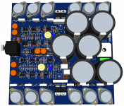
Just to illustrate, I'm joining a visual of one single board version I had done, long ago now. That was including line receiver at the input for fully differential driving, and all on a single board, with the PSU. I would like to see this project get somewhere. It's not very far from prototyping..
But I miss it and I was making a little time to do a little something, specifically I re-visited the simulations for the 3055 based grounded bridge (John Ellis') and although I have never been able to get the VI limiter to work properly on it, whatever values calculated never actually ended up being effective. So I was again giving some thoughts about an alternative to the regular VI limiter, which would do more than just plain limiting, and that alternative would be an input muting/limiter that can be triggered by "looking" at the differences between the inputs at the diff stages. This can easily be done by a plain opamp, looking at each diff amp input, without disturbing anything with a high input impedance. Any signal that is beyond legitimate, including what happens when the amp's output gets shorted, is ground to take some measures.
Now there are 2 ways this could be handled at the input, either we just engage a mute of the whole input signal and a timeout, to allow gradually to bring the signal back, and if the fault is still present, it would just mute again to try this later, for as long as the fault remains.
The other way, which would be quite nice to have, is an input signal limiter, that only engages when distortion was detected by the opamp monitoring the diff amp's signal differences. This would be nice because it would also work for clipping situation where we don't really want to mute everything and just limit to keep the issue under control.
Anyway, while pondering on this, I was also trying to measure the margins on the grounded bridge, using the probe (forgot the name), which I've been using on other amps, but that seem to provide faulty data on this bridge, most likely because I'm not using it right.
And I was hoping to get some pointers on how to probe for the margins on that grounded bridge topology.
The main thing is, this bridge essentially has 2 feedback loops, not mentioning the advanced compensation beyond plain miller, and those loops aren't nested. So then, where is the probe to be inserted to get proper phase measurements?
I was inserting it in the feedback return path coming from the output bus on the output stage on the high side (not the grounded low side), coming back to the feedback input, where the compensation and negative input network is.
The measurements are way out of whack (in sims, ltspice), so something ain't right and I have to be doing this wrong.
I won't have much time to spend on this for now, but at least I'd like to get this under control so I could tweak the proper values for the compensation.
I had done several versions of pcb layout already, way back when I was still able to spend time on this, so I actually have a few possible prototype builds that could be made, as long as proper compensation at least is applied, so as to minimise issues (no oscillations).
Just to illustrate, I'm joining a visual of one single board version I had done, long ago now. That was including line receiver at the input for fully differential driving, and all on a single board, with the PSU. I would like to see this project get somewhere. It's not very far from prototyping..
Attachments
- Home
- Amplifiers
- Solid State
- Amplifier based on 2N3055