Perhaps there is one other thing that could be done. If they are available where you are and cheap enough, there are the 2N3442 and BDX20.
Those are possible drop-in 3055 replacements.
They're very similar in most respect: same power dissipation, same case, a little less gain for the 3442, and only 10A instead of 15, but that lower current handling isn't an issue in this case, and most of all, the lower current trades for much higher Vce0, as they're 140V rated.
The one thing that's kind of bad with those is they're slower, much slower.
But I've used power amps before based on those 3442 devices, and they worked just fine, full range.
Although they handle less peak current than the 3055, they're still pretty rugged in comparison, and with 140V guaranteed breakdown voltage, there is no way you'll break them that way. So big heatsink and here you go, with higher rails.
The key is to find them, and if they're cheap enough.
They are still available on mouser for example, but only the 2N3442 and not its BDX20 complement. It all depends on what's available where you are.
I have old stock of all those devices, 3055s, 2955s, 3442, bdx20, bdx18, 2n3773, etc... All from the 60s and 70s, so no fakes for sure.
That 2N3773 could also be possible, if you could also find its complement the 2N6609, but that may be unlikely, and if they're cheap enough anyway.
at the last i can take conclusion of this circuit
2N30055/MJE2955 is not a great solid state amplifier but still the best for small home audio entertainment
for better result, fixing some parts like bootstrapping or final transistor for better result
changing transistor like what you said is the best option for longer lasting operation time at full range frequency
higher rails is not best option but it can be done for avoiding clipping but taking calculation for lower current trades for much higher Vce0, as they're 140V rated
2N30055/MJE2955 is good transistor but only for small devices
making this new one on this time looks like an impossible cause there are so many fakes out there
best result is using 2N3442 and BDX20
thank you very much...
")
you guys have been answering my question and my problem...
i don't know how to say it but once again thank you very much
and i can not imagine how precious those ORIGINAL transistor from 60s and 70s you have that's very old than me
Last edited:
I did an update to an old 1980's Maplin 225WRMS using 2n3055 and mj2955.
I used MG6330 and MG9410.
Those are hard to find and quite expensive.
They do need 10 ohm base resistors to stop oscillation though.
I bet. Those puppies are plenty fast and any circuit that was designed for the slower devices would certainly require some adjustments to prevent that.
One other thing is they're TO3P, so how did you handle the change of case?
Those are hard to find and quite expensive.
I bet. Those puppies are plenty fast and any circuit that was designed for the slower devices would certainly require some adjustments to prevent that.
One other thing is they're TO3P, so how did you handle the change of case?
RS Components sell them. £3 to £4 each.
It was hard work finding those alternatives.
They are the same case as 2n3055/mj2955 TO3 package.
Those are hard to find and quite expensive.
I bet. Those puppies are plenty fast and any circuit that was designed for the slower devices would certainly require some adjustments to prevent that.
One other thing is they're TO3P, so how did you handle the change of case?
can it be???
using 10ohms???
per final transistor or only one before final transistor???
#update :
PUT 10 OHMS to the base of positive side final transistor at the base of 2N3055
only one after TIP31C...
the result so fantastic, positive side and negative side are balanced!!!
try it
Last edited:
I use 10r on each base of output transistors from drivers.
I did an amplifier with 2 pairs on the output and it sounded very good.
10R and watt rating??? 1, 2 or 5???
using sims my amplifier circuit will be balanced if i put only one 10R 2watt before base final transistor
10R and watt rating??? 1, 2 or 5???
using sims my amplifier circuit will be balanced if i put only one 10R 2watt before base final transistor
1 watt is fine.
Yes, one 10r per output transistor.
I have old stock of all those devices, 3055s, 2955s, 3442, bdx20, bdx18, 2n3773, etc... All from the 60s and 70s, so no fakes for sure.
That 2N3773 could also be possible, if you could also find its complement the 2N6609, but that may be unlikely, and if they're cheap enough anyway.
The reason to use those older types is if you already have them and need to put them to use. No sense in looking for them - if you have to buy all new just buy MJ15024/5 and be done with it. MJ15015s are getting expensive. 2N3442s aren't cheap either. Many manufacturers are discontinuing the 3055. But I have a boatload of old types of all sorts and so do a lot of others here. They're paid for and using them in these experimental old designs doesn't use up the stash of MJ2119x's that are necessary for servicing real pro equipment or building the big bruisers.
Have 3773's and looking for 6609's ? Use MJ15004. For practical purposes they are the same. True, ratings are different. But it will act like a 6609 and the ON Semi version will likely take 1.5A at 100 volts. The alternative is a "6609" from Central Semiconductor at over ten bucks each. Are they real? Don't know. I have used Mospec branded 2N6609s and had no trouble with them. But they were less than 4 bucks apiece in 1990. Paying $10 defeats the purpose. I'd just buy 15004's today. Of course I did find about 30 pieces NOS MJ15004 (and cracked one open to verify) for $2.50 a pop and, well when you make that sort of find you just snatch them up. Finding stuff like this over 20-odd years is how you get a stash of older types.
first.This is what i want from all of you guys...
I will make this one reaching pure 300 watt stereo not bridge...
I will change the AC voltage from 24V AC to 30V AC
I will change trafo from 10Amps to 20Amps
So, is that dangerous or not?(2N3055 MJ2955 datasheet said that is still safe area)
But, what about other transistor, D400 and A733?
TIP31C and TIP32C(final transistor driver) datasheet said it is ok...
Please tell me, so i can follow you...
you need approximately 5 to 6 times the output power for the total device Pmax.
If you want 300W of maximum power output you need ~1500W of devices in that channel.
if the 3055 is 115W for Pmax @ 25°C then you would need 7pairs to get reliable 300W power.
second.
you need to keep the supply rails under half the Vceo.
If the 3055 has a Vceo of 80V then you can use upto ±40Vdc. but that is the maximum. A more typical operational voltage would be around ±35Vdc to allow for times when the voltage is higher than normal.
third.
assess the voltage sag of the PSU when delivering maximum power. I'd suggest allowing 4Vsag to 8Vsag
fourth.
assess the voltage lost through the amplifier when delivering maximum power.
I'd suggest allowing 3Vloss to 6Vloss.
Starting with 35Vdc and subtracting Vsag and Vloss you end up with a maximum output voltage of around 25Vpk
if you want 300W then the current peak that needs to be delivered will be 2*300W / 25Vpk = 24Apk
The load would need to be 25Vpk/24Apk = 1.04ohms
The ONLY way to get 300W from 80Vceo 115W devices is to use ±35Vdc and 7pairs of devices and to use a 1ohms load.
My advice:
forget it until you learn how to design power amplifiers.
first.
you need approximately 5 to 6 times the output power for the total device Pmax.
If you want 300W of maximum power output you need ~1500W of devices in that channel.
if the 3055 is 115W for Pmax @ 25°C then you would need 7pairs to get reliable 300W power.
second.
you need to keep the supply rails under half the Vceo.
If the 3055 has a Vceo of 80V then you can use upto ±40Vdc. but that is the maximum. A more typical operational voltage would be around ±35Vdc to allow for times when the voltage is higher than normal.
third.
assess the voltage sag of the PSU when delivering maximum power. I'd suggest allowing 4Vsag to 8Vsag
fourth.
assess the voltage lost through the amplifier when delivering maximum power.
I'd suggest allowing 3Vloss to 6Vloss.
Starting with 35Vdc and subtracting Vsag and Vloss you end up with a maximum output voltage of around 25Vpk
if you want 300W then the current peak that needs to be delivered will be 2*300W / 25Vpk = 24Apk
The load would need to be 25Vpk/24Apk = 1.04ohms
The ONLY way to get 300W from 80Vceo 115W devices is to use ±35Vdc and 7pairs of devices and to use a 1ohms load.
My advice:
forget it until you learn how to design power amplifiers.
Hey...
That circuit is not my design!
And i am still learning and know about amplifier design
And that kit have 2 channel also it was one of my old amplifier, about 5-6 years ago
Then i mean 300 watt stereo...
That kit itself come to me with 2channel or stereo
On the box, the description said 300 watt stereo using 24VAC
you can be an "informed customer", or a gullible customer.the description said 300 watt stereo using 24VAC
That's your choice.
I know that that advertising is untruthful !
You have had time to become "informed", but you still cling on to a completely untruthful claim.
You DON'T know how to design amplifiers despite what you post
know about amplifier design
As I'm trying to tweak some models, I'm testing them on some old sims.
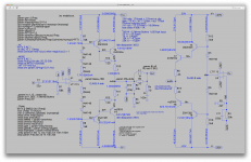
Here is a sim for an other interesting amp topo, a hybrid of a Class A with a Class B, based on an old (1982) elektor circuit.
A few things were changed to make it work right and have decent results.
The sim runs nicely even with the un-tweaked models, that I included in the sim file itself to avoid calling up an external file. So it should run right out of the box.
The Class A amp runs on only 5V rails as it is in that sim, and the Class B runs on 20V rails. The Class B makes the Class A rails float, so although the Class A amp runs with a rather "rich" bias at about 1A in the outputs, the dissipation is less than 5W in each device (power ones), and the dissipation in the Class B side is minimal, with just about no bias at all.
This amp is fairly simple, with a fairly low part count, so this could make a rather easy build, and it's a 3055/2955 amp.
I wonder if it would be better or not to have separate heatsinks for both sides...
In that sim I used the Linear LT1115 opamp, which is very low noise, low distortion and works great, but it's not too hard to try out others if need be.
There are slight differences with the original elektor published circuit, as I found that when I tried to simulate it as it was designed, it wouldn't work quite right and performance was nothing like a Class A amp should be.
Now this is still only a small 3055 amp, but the results look pretty nice.
It's not a powerful beast, it can reach a little more than 18Wrms on 8ohms (resistive), but by then it's the onset of clipping and the thd starts rising a little before that.
However, it performs rather well at 15Wrms, and I tried it at many power levels, starting with tiny input at 1uV, and it looks pretty nice all the way up.
With the reduced dissipation on the Class A side due to the low rails, and almost nothing at idle from the Class B side, it shouldn't get overly warm, with decent sinks, and overall the dissipation should remain lower than what a Class A amp.
It's a weird topo, with 2 amps of different class, the rails float, kind of like in a class H, but it's not a class H.
The original design had the class B side extremely "barren" (spartan), and the thd wasn't so nice.
This altered design does use a few more parts on the B side, but not much, just 2 diodes and 4 resistors. Nothing to break the bank and add much complexity.
I tried to keep that part count as low as possible for a good compromise in performance. It can be improved further, at the cost of a few extra parts, and the thd can the be made to drop well below 1ppm at all frequencies.
The one thing that's a bit more complex is the dual supplies, and the high rails one could go to the opamp's limit at 22V eventually, for a few extra watts.
Perhaps the high rails could be made so a higher voltage could be given to the B side, while the opamps stay at 20V, for even more watts, but I haven't tried that.
The small part count could make for a small PCB. Maybe 2 heatsinks, but probably not too big.
Attachments
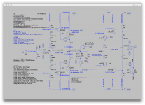
Your output Zobel does not seem right.
You have 10r R9 plus 10r Rz in series with 100nF. That rolls in at ~80kHz. That seems far too close to the audio band.
better change that by adding 8r+47nF at the output.
Then change R9 to 3r3 and change Rz to 4r7 and keep Cz @ 100nF
This will give a good Zobel (equivalent to 4r+147nF) at a higher frequency (~270kHz) and attenuate RF coming in via the speaker cables.
better change that by adding 8r+47nF at the output.
Then change R9 to 3r3 and change Rz to 4r7 and keep Cz @ 100nF
This will give a good Zobel (equivalent to 4r+147nF) at a higher frequency (~270kHz) and attenuate RF coming in via the speaker cables.
Actually, I was reading (again) one of Cherry's papers where he mentions the zobels and the 2 forms suggested by Thiele, and thought about using the one that has no resistor in parallel with the coil, so I would just move the zobel in and cut out that extra res.
Your option would also work of course. Maybe a comparison, to see what works best...
However, while testing it further, as I had not tried it before with anything else but that 8ohms resistor load, I tried a lower 4ohms load and that makes it clip much too early.
So I'm trying to figure why it's clipping early. I thought maybe the opamp's inner limit was doing it, and although it seems fairly close, I'm not certain that's it.
I found out the class A bias also wasn't quite high enough for the full power.
It should be about half that of the peak load current, and at about 1amp, that falls a little short, which can explain a little of the rising thd a little before it actually starts clipping.
Raising that bias current in the outputs to about 1.18amps (on their emitters), brings it closer to optimal. I tried a range of bias and that's about optimal there. Anything higher and the thd rises again.
Then I thought perhaps that also had something to do with the reason for clipping earlier on 4ohms, but raising it beyond 1.18amps has adverse thd effect, and it doesn't solve the early clipping anyway.
So the reason for the earlier clipping on 4ohms remains a mystery so far.
It really needs to work right on 4ohms, so that would represent the worst possible impedance situation under a difficult 8ohms load. Reactive and all.
I was also entertaining the option of separating the high rails on the B side from the opamp supply rails, so the opamps could remain at 20V, and perhaps have the high rails at something like 40V.
The only way to make this work is to alter the B side to have a bit of gain, in this case about 2 would work. But that complicates the B side some more and there could be instability issues...
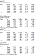
I tried both versions:
R9 @ 3.3 and 4.6 on the zobel (keeping Cz 100n)
no R9, Rz @ 8 and move the zobel "inside"
Both options give improvements at the higher frequencies, about the same magnitude, and change nothing at the low end.
The highest thd is at the low end at a bit more than 30ppm.
Still hifi, but perhaps this can be improved.
Here, I had not adjusted the bias on this one to the more optimal value.
Raising it to ~1.18amps is better.
But the low end remains unchanged, same thd, and more than at the high end.
Maybe a bigger input cap might help a bit.
Not bad for a 3055 amp.
The increase in bias adds less than 1W per device of dissipation, still well below 6W (idle) per device. Still easy enough to dissipate, for a class A.
The peak dissipation in each device at full power is close to 4 times the idle, and the average almost twice. All well within the 3055 capabilities.
Running the A side at 5V really helps cutting down on dissipation.
Attachments
You got that right!
I just ran the tian probe to see what the open loop gain looks like and get a reading on the phase and gain margins.
Amazingly, there isn't a huge amount of phase shifting in the useful band, so at unity gain, we're still at about -100 degrees of shift, giving about 80 degrees of phase margin. At least there's that. Then the phase shifting kicks in higher gear but not enough to bother it, and we end up with decent gain margin of about 15.6db. That part isn't bad and the amp seems stable.
But the oddity is at 10hz. It's funny how the closed loop gives such a huge gain spike right there at 10hz, from the 32 and some db nominal gain, to close to 45db at the height of the gain spike. And the open loop instead has just about zero gain at that same 10hz, and a big phase reversal happens right there.
I wonder what causes this, maybe the bootstrapping?
Since this amp is so similar to yours, even with the extra pre-driver stage, it probably behaves similarly.
Perhaps mooly could use his sim that he made earlier and let us know how that one behaves.
at the last, i will make a declaration about my circuit...
i will using it till i make other else
2N3055/MJE2955 is not good choice but for lower cost this one still better
of course this one is not very loud for my home and also for my neighbors
i mean crowded level cause the place where i leave is densely populated area also the walls of the houses are sticking together
well, i will take your words
your words is take for granted the ability of this amplifier and don't expect more
thank you very much
By the way, those last sims were done after I tweaked the models a bit.
Increasing the VAF to more real values worsen the thd figures somewhat.
I raised the 3055 VAF to 150. A conservatively more realistic value. As John Ellis measured on a real part about 181, we're not far off and better than the small amount that was there before and that was wrong.
Not knowing what the 2955 has, I arbitrarily put 140 for VAF.
More parameters need tweaking. Those models are modpex (nuff said)
your words is take for granted the ability of this amplifier and don't expect more
Well, you simply believed false advertising that's all. You wouldn't be the first one to fall for it.
But now I suspect you're getting more informed and can figure out when you're being lied to.
- Home
- Amplifiers
- Solid State
- Amplifier based on 2N3055