.

Otopia Project - new idea amp
so how give a short intro ... i wonder
when i say
'new idea amp' this means
the concept as a whole is new
most every detail can be found everywhere
but isnt this typical for amplifier designing:
most 90% has been used before
it goes like this for Carlos destroyer X
as well as for Nelson Pass & Grham Maynard or BoraOmega
it is your special mixture, blend
that can make & bring something new & unique
... if you are lucky
let me give a few basic information:
------------------------------------------------------------------------------
- bjt & jfet transistors
- some precisision current sources, jfet based
- diff pair input, a la other lineup posted designs last 12 months
- something different from normal Op-Amp style with FB
- means no global feedback from output to input pair
- application, in this case, pre amps, headphone amps
- +/- 15 VDC supply for this first version
------------------------------------------------------------------------------
why i wanted to share
was the attached FFT fast fourier analys
===>> what we want, isnt it
... i just had to show you
....................................................
of course i be back with more
but no hurry - i just got this idea to this circuit a few hours ago
lets see where we are at end of summer
in about 4 months from here
lineup
Attachments

Mr. Lycksele how about do something about your secret amp?
http://lineup.awardspace.com/project02.html
I think it's much better to draw a schematic with the idea. The possible pros and cons of your new concept?
http://lineup.awardspace.com/project02.html
I think it's much better to draw a schematic with the idea. The possible pros and cons of your new concept?
New Lineup Audio website style
i decided to give http://lineup.awardspace.com/ a face-lift
thanks for your inspirations Nelson & peranders
( I actually had to torrent downloaded goldfrapp special edition .. it is Not Bad music! )
New Lineup Audio style will include:
1. new colours in a soulful shade of blue ..a song title
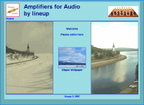
2. a new Otopia Wallpaper, to match this new-amp-idea
3. detailed description of thinkings behind - along with outcome, result of the same
4. Dated 2007-06-xx, update versions, as eventual improvements are made
5. But dont you worry. Most of my stuff will be faithfully posted here, too.
See attachment for the new look of my website.
The Otopia Wallpaper 1024x768 is a photo I took this winter April 2007
when I visited my old & crippled mother(85) in the high mountains
in beautiful swedish ..11. Highlands ..songtitle from Bob Dylan album-97: Time Out of Mind
Enjoy!
lineup - you man in sweden
lineup said:Otopia Project - new idea amp
short intro ...
------------------------------------------------------------------------------
- bjt & jfet transistors
- some precisision current sources, jfet based
- diff pair input, a la other lineup posted designs last 12 months
- something different from normal Op-Amp style with FB
- means no global feedback from output to input pair
- application, in this case, pre amps, headphone amps
- +/- 15 VDC supply for this first version
------------------------------------------------------------------------------
lineup
i decided to give http://lineup.awardspace.com/ a face-lift
thanks for your inspirations Nelson & peranders
( I actually had to torrent downloaded goldfrapp special edition .. it is Not Bad music! )
New Lineup Audio style will include:
1. new colours in a soulful shade of blue ..a song title
2. a new Otopia Wallpaper, to match this new-amp-idea
3. detailed description of thinkings behind - along with outcome, result of the same
4. Dated 2007-06-xx, update versions, as eventual improvements are made
5. But dont you worry. Most of my stuff will be faithfully posted here, too.
See attachment for
the new look of my website.The Otopia Wallpaper 1024x768 is a photo I took this winter April 2007
when I visited my old & crippled mother(85) in the high mountains
in beautiful swedish ..11. Highlands ..songtitle from Bob Dylan album-97: Time Out of Mind
Enjoy!
lineup - you man in sweden
Attachments
I need you personal mail adress urgent Line up
I have an important message in audio MP3...size is 3.5 Megabytes and the one is returning into your Opera mail.
Please, goto:
panzertoo@yahoo.com
informing another E mail adress that can hold this data size.
regards,
Carlos
I have an important message in audio MP3...size is 3.5 Megabytes and the one is returning into your Opera mail.
Please, goto:
panzertoo@yahoo.com
informing another E mail adress that can hold this data size.
regards,
Carlos
Thank you, but i have lost lineup mail adress.
The one that returned, the message i have already tried to send, and have returned, was to Opera mail i think.
I will wait him to send me an optional mail adress, or his old and good ftp adress.
The message is important, urgent, and will be something that will be important to Line up.
Unfortunately, seems to me that he is sleeping whole day... alike a bear.
His place is cold, and maybe dark in this period of the year i suppose....hummmm, very good to sleep.
regards,
Carlos
Hello.lineup said:.
let me give a few basic information:
------------------------------------------------------------------------------
- bjt & jfet transistors
- some precisision current sources, jfet based
- diff pair input, a la other lineup posted designs last 12 months
- something different from normal Op-Amp style with FB
- means no global feedback from output to input pair
- application, in this case, pre amps, headphone amps
- +/- 15 VDC supply for this first version
------------------------------------------------------------------------------
/snip/
....................................................
of course i be back with more
but no hurry - i just got this idea to this circuit a few hours ago
lets see where we are at end of summer
in about 4 months from here
lineup
Finally got some time to take this idea a bit further.
I will now post the results of current version.
Whether I will reveal all details of my unique circuit, at this place,
or somewhere else
is very much dependent of the diyaudio forum members themselves.
If there is any call for it.
Some little demand for me, my Amplifier stuff and my findings
=============================================
This project OTOPIA is based on several circuits I have published here at www.diyaudio.com in other topics wit my schematics.
The name is losely chosen because there are some OTA functions done.
( Operational Transconductance Amplifier )
I like these OTAs very much and have studied CA3080 in detail.
Other topologies, ideas, designers
that has influenced Otopia is:
- AD767
- My own version of AD767, 'New JFET input Hifi Amplifier'
- Walt Jung articles, for example Diamond Buffer
- My own work on high quality Class A Follower Output stage,
... with fellow member Jerluwoo
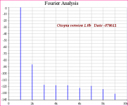
This is what current version Otopia HEX Power,
will produce in a Fourier Analyse of harmonics 1-9.
Power output is 1 Watt into 5 Ohm
Gain is as told, +20 dB
This version is a stripped down version,
with AS LOW NUMBER of transistors as possible.
I expect the harmonics spectra to stay as is
but at a much lower level, once I have optimized my circuit.
The important with this amplifier, is NOT the actual THD level,
but the relationship between the 9 harmonics.
Most 2nd and less of the other!
Regards
halojoy
Attachments
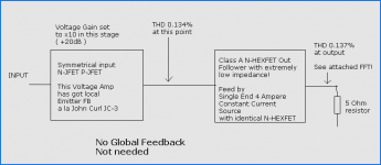
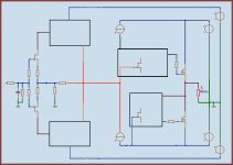
Here is a
BLOCK-DIAGRAM overview of the concept of this amplifier.
It should be noted,
almost all distortion comes from the first Input stage.
And so the FFT Harmonics shown in previous post
are the Harmonics of the
Symmetrical N-JFET + P-JFET input Voltage Amplifier,
with its local Emitter FB.
If there are any questions, I may give away a few details more.
But this amplifier project is far from done.
In the End when things looks 99% right
it is time to publish.
Here or Where Ever else.

Regards
lineup
BLOCK-DIAGRAM overview of the concept of this amplifier.
It should be noted,
almost all distortion comes from the first Input stage.
And so the FFT Harmonics shown in previous post
are the Harmonics of the
Symmetrical N-JFET + P-JFET input Voltage Amplifier,
with its local Emitter FB.
If there are any questions, I may give away a few details more.
But this amplifier project is far from done.
In the End when things looks 99% right
it is time to publish.
Here or Where Ever else.
Regards
lineup
Attachments
Otopia input and VoltAmp FB .. a la ZenQuito!
sorry
My remembering failed me.
The input and Local VoltageAmplifier FB is not as in John Curl JC-3.
He has used Sym JFET input alright, but in a more conventional way.
(Dual symmetrical JFET differential.)
-------
What amplifier I meant was the ZenQuito Evolution.
If you take the feedback BEFORE the output stage ( BUZ900 ) in the attached circuit,
( that is between the both 68 Ohms resistors ),
you will have how is my emitter feedback between N- and P-JFET input devices.
See my attachment, please, for correct information.
Shows one Zenquito Evolution, with best possible modern Audio FET Technology Devices!!
Regards
lineup - The amplifier designer from Sweden
Attachments
Hmm,interesting..
I kinda like Goldfrapp..
Nelson Pass said:My dog needs new ears....
"Utopia" by Goldfrapp
I kinda like Goldfrapp..
Status report April 20th 2008.lineup said:
This is what current version Otopia HEX Power,
will produce in a Fourier Analyse of harmonics 1-9.
Power output is 1 Watt into 5 Ohm
Gain is as told, +20 dB
This version is a stripped down version,
with AS LOW NUMBER of transistors as possible.
I expect the harmonics spectra to stay as is
but at a much lower level, once I have optimized my circuit.
The important with this amplifier, is NOT the actual THD level,
but the relationship between the 9 harmonics.
Most 2nd and less of the other!
Regards
halojoy
> Power output is 1 Watt into 5 Ohm
> Gain is as told, +20 dB
Gain is now raised to +23dB ( x14.14 )
The nominal Output power is targetted to 16 Watt RMS into 5 Ohm.
This means ~9Vrms output and input sensitivity for this will be:
9/14.14 ~ 0.640 Vrms in.
------------------------------
12.65 Vpeak output into 5 Ohm requires peak current out:
+- 2.53 Ampere.
To make sure we have margin! to clipping
I will go for 2.53A is 80% of maximal output current.
(I have noticed most true Class A stages start haveing problems and begin distort in area 75-85% of idle current cpacity )
So the lower CCS through HEXFETs will be delevering:
2.53A x 100/80 = 3.20 Ampere Single Class A Current.
I havent decided if to use 2x12 VAC or 2x15 VAC Transformer for output.
I can make it work with both, even is if is easier, of course, with 2 x 15 V Trafo.
( The HEXFET Gate driver circuits needs some voltage drops ).
=======================================
> This version is a stripped down version,
> with AS LOW NUMBER of transistors as possible.
>I expect the harmonics spectra to stay as is
> but at a much lower level, once I have optimized my circuit.
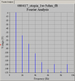
And this gave nice Fourier spectra, but at a high THD, 0.137% (1w in 5 ohm)
Today I added the 6 BC550C/BC560C transitors needed to optimize Voltage amplifier.
These are low-noise bipolar, to support the JFETS, with improved output current handling
of the first BLOCK ... the x14.14 Voltage amplifier.
--------------------------------
The Test Result Today:
THD 0.137% is now at a more reasonable level:
THD 0.010%
The 2nd Harmonics is still most of this, and each following
3rd - 4th - 5th - 6th .. are still steadily in falling sequence!
-----------------------------
I have acheived what I aimed for.
This FIRST VERSION of my amplifier shows the simulated behavior I was after.
Ever since my first post here in my new design:
Otopia Project - new idea amp
I expect to trim some current levels for ever a bit better MultiSim test results
for my SECOND VERSION. Maybe later next week.
------------------------------
Attached is a
block diagram of my MODEL. There are 4 Sub-BLOCKS to The 2-amplifier approach with No-Global Feedback,
but only feedback within each block.
Notice that all 4 blocks INPUTs are controlled by high Impedance JFET Transistors.
I have used the Very standard 2SK170GR.
And not some rarely used exotic device creatures
If they are good enough for Nelson Pass, then .........
Regards.
halojoy - wishes some clever would read .. and get what he is doing
Attachments
I have the parts to try, but i would like, in advance
to see it already constructed and to listen, in advance, some review about.
Seems to be excelent, but real world surprises us...the circuit is an enormous promisse of quality.
Can you please, inform if someone have built and inform also where to see the picture?
regards,
Carlos
to see it already constructed and to listen, in advance, some review about.
Seems to be excelent, but real world surprises us...the circuit is an enormous promisse of quality.
Can you please, inform if someone have built and inform also where to see the picture?
regards,
Carlos
Otopia 2008-04-22 OpenLoop Test
hi
Otopia 2008-04-22 OpenLoop Test.
I continue trying to improve my circuit.
Today's version I consider very promising.
This is all about the first BLOCK = Voltage amp.
This is a new setup (some new components), but uses 2SK170GR input, as before.
But I exchanged BC550C/560C for BCP53-16/56-16 to be able increase current.
Almost double as much Voltage amplifier output current capacity.
Theoretical max output is now something like +- 13 or 14 milliAmpere peak.
============================
People sometimes asked me for OpenLoop figures and data.
I do not know what this should be good for
.. at least I, never use my high gain amplifiers at OpenLoop output.
But Anyway, here you are:
By the way, I intend to use IRFP2XXN output devices.
I can buy them from a trusted supplier here in Sweden www.elfa.se
Elfa has got EUROPE service and Online catalog in many Languages!
I see one big diffrence between, for example,
old IRFP254 and the new and improved TO-247AC IRFP254N
is the Max Juntion Temperature. 175 C now instead of 150C.
This means higher power handling values.
halojoy - still believes in this model - his new idea amplifier
hi
Otopia 2008-04-22 OpenLoop Test.
I continue trying to improve my circuit.
Today's version I consider very promising.
This is all about the first BLOCK = Voltage amp.
This is a new setup (some new components), but uses 2SK170GR input, as before.
But I exchanged BC550C/560C for BCP53-16/56-16 to be able increase current.
Almost double as much Voltage amplifier output current capacity.
Theoretical max output is now something like +- 13 or 14 milliAmpere peak.
============================
People sometimes asked me for OpenLoop figures and data.
I do not know what this should be good for
.. at least I, never use my high gain amplifiers at OpenLoop output.
But Anyway, here you are:
1 mV RMS input
1 kHz normal sinus signal
5 kohm load, pure resistive
( Somthing like real load,
mainly to drive my 2 Emitter Feedback resistors,
which is the main part of the load, as the Power follower has got JFET input and is an easy load))
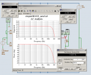
Result: (see also my Screenshot of this OpenLoop Simulation)
4.286 V RMS Output voltage across 5 kohm, ( +- 860 uA )
Gives an open loop gain of 4286 ( +72.6 dB ) into 5 kohm
-3 dB at 800 kHz ( 0.8 MHz ) .. see Screenshot AC analyse
THD: 1.007 %
... Harmonics:
2nd: -40dB
3rd: -80 dB
4th: -115dB
The other are all below -140dB
By the way, I intend to use IRFP2XXN output devices.
I can buy them from a trusted supplier here in Sweden www.elfa.se
Elfa has got EUROPE service and Online catalog in many Languages!
I see one big diffrence between, for example,
old IRFP254 and the new and improved TO-247AC IRFP254N
is the Max Juntion Temperature. 175 C now instead of 150C.
This means higher power handling values.
halojoy - still believes in this model - his new idea amplifier
Attachments
- Status
- This old topic is closed. If you want to reopen this topic, contact a moderator using the "Report Post" button.
- Home
- Amplifiers
- Solid State
- Otopia Project - new idea amp