Otopia Project - Output HEXFET Driver Modules.
Hello again")
I decided to go for 2x12 VAC toroid trafo.
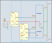
For the Follower, The HEXFET Class A output BLOCK.
I use +-15 Volt in my Test Circuit.
The real life value may be 15-17 VDC something, very much dependent on TRAFO Size
and also rectifier and PSU filtering technique.
To make output stage
- have higher effiency and
- 4 Volt Gate-SOURCE stay uneffected by output voltage/current levels
.. I use my floating MOSFET Driver Modules.
( Yellow in my figure below )
Biased from The +- 24 VDC supply, that powers the BLOCK1 Voltage amp, too.
I have used Op-Amp style to show the Equivalent operation of my modules.
As this is somthing most diyAudio members can relate to and understand.
I do not write for only the Audio Engineers at our forum
and those with high technical terms and the amplifier university mumbo jumbo langauge.
Probably they have use those words/terms, when publish their patents and white, red or blue papers rated 5 stars out of 5
-------------------------------------------------------------------------------------
Equivalent.
Means for examples, there is in reality only one 2SK170GR N-JFET for 'op-amp' input.
Modules are supplied by 30mA (N-JFET based) CCS, constant current source.
I will not now go into the technical aspects, why I did it like this.
===============================================
Okay.
Here you are.
My Output BLOCK2. To show the Basic setup I use.
In colours layout
to make your eyes easily see what is going on.
lineup - regards from Sweden
Lineup Audio Lab http://lineupaudio.freehostia.com/
===============================================
PS. Old chaps!
1951 was a very good year ...
Destroyer of Brazil and Nelson Pass of United States of America
I have turned ON my forum email.
Just for the Two of you
If you are no friend of me, you should really not bother to request any of my Intellectual Properties. I reserve me fully the right to publish, if and when and where I want. If I feel some place is not right for such goodies, like my ideas, there are plenty of alternatives in 1.000 of websites around this our internet world.
Like for example my own websites.
See my current signature for additional info.
DS.
Plineup said:
12.65 Vpeak output into 5 Ohm requires peak current out: +- 2.53 Ampere.
So the lower CCS through HEXFETs will be delevering:
2.53A x 100/80 = 3.20 Ampere Single Class A Current.
I havent decided if to use 2x12 VAC or 2x15 VAC Transformer for output.
I can make it work with both, even is if is easier, of course, with 2 x 15 V Trafo.
( The HEXFET Gate driver circuits needs some voltage drops ).
--------------------------
--------------------------
I have used the Very standard 2SK170GR.
And not some rarely used exotic device creatures.
If they are good enough for Nelson Pass, then .........
Hello again
I decided to go for 2x12 VAC toroid trafo.
For the Follower, The HEXFET Class A output BLOCK.
I use +-15 Volt in my Test Circuit.
The real life value may be 15-17 VDC something, very much dependent on TRAFO Size
and also rectifier and PSU filtering technique.
To make output stage
- have higher effiency and
- 4 Volt Gate-SOURCE stay uneffected by output voltage/current levels
.. I use my floating MOSFET Driver Modules.
( Yellow in my figure below )
Biased from The +- 24 VDC supply, that powers the BLOCK1 Voltage amp, too.
I have used Op-Amp style to show the Equivalent operation of my modules.
As this is somthing most diyAudio members can relate to and understand.
I do not write for only the Audio Engineers at our forum
and those with high technical terms and the amplifier university mumbo jumbo langauge.
Probably they have use those words/terms, when publish their patents and white, red or blue papers rated 5 stars out of 5
-------------------------------------------------------------------------------------
Equivalent.
Means for examples, there is in reality only one 2SK170GR N-JFET for 'op-amp' input.
Modules are supplied by 30mA (N-JFET based) CCS, constant current source.
I will not now go into the technical aspects, why I did it like this.
===============================================
Okay.
Here you are.
My Output BLOCK2. To show the Basic setup I use.
In colours layout
to make your eyes easily see what is going on.
lineup - regards from Sweden
Lineup Audio Lab http://lineupaudio.freehostia.com/
===============================================
PS. Old chaps!
1951 was a very good year ...
Destroyer of Brazil and Nelson Pass of United States of America
I have turned ON my forum email.
Just for the Two of you
If you are no friend of me, you should really not bother to request any of my Intellectual Properties. I reserve me fully the right to publish, if and when and where I want. If I feel some place is not right for such goodies, like my ideas, there are plenty of alternatives in 1.000 of websites around this our internet world.
Like for example my own websites.
See my current signature for additional info.
DS.
Attachments
hi
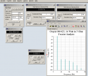
2008-04-25 Otopia Project Status Report.
The output stage with my special HEXFET Drivers shows excellent data.
I mentioned in an earlier post, that the output BLOCK2
has got very low impedance.
Today I measured this, at several output levels.
where output BLOCK adds practically no % THD,
to what the first BLOCK (Voltage amplifier +23dB) contributes.
THD is ~ 0.058% at Power Input, as well as Output
For 16 CLASS A Watts RMS into 5 Ohm.
The Power Amplifier block looks like having several 100 kOhm input impedance.
Of course by the fact it has got 2SK170 JFET input transistor ...
But I am not 100% sure what is best method to test / calculate input impedance.
Anybody have some hints for me
I would be glad to know how you estimate input impedance of your power amplifiers.
thanks
For one of today's tests .... with Fast Fourier harmonics
See attachment, please.
Regards
halojoy
2008-04-25 Otopia Project Status Report.
The output stage with my special HEXFET Drivers shows excellent data.
I mentioned in an earlier post, that the output BLOCK2
has got very low impedance.
Today I measured this, at several output levels.
This is also verified at a test,The output follower Class A block
with its local N-JFET controlled feedback sensor,
has an impedance (from input to output) like:
0.00098 - 0.00104 Ohm
So, for a signal of 10.000 Volt peak at power folllower input, there will be
~9.998 Volt across the 5 Ohm LOAD
and the remaining
~0.002 Volt across the output amplifier
where output BLOCK adds practically no % THD,
to what the first BLOCK (Voltage amplifier +23dB) contributes.
THD is ~ 0.058% at Power Input, as well as Output
For 16 CLASS A Watts RMS into 5 Ohm.
The Power Amplifier block looks like having several 100 kOhm input impedance.
Of course by the fact it has got 2SK170 JFET input transistor ...
But I am not 100% sure what is best method to test / calculate input impedance.
Anybody have some hints for me
I would be glad to know how you estimate input impedance of your power amplifiers.
thanks
For one of today's tests .... with Fast Fourier harmonics
See attachment, please.
Regards
halojoy
Attachments
a quick and dirty way i've done input impedance at a specific frequency was: hang a large pot set to zero resistance in series with the signal generator's input to the amp. turn the pot until the circuit under test output drops to half. measure the pot - that's the circuit's input impedance at the test frequency.
not the most accurate, but it's quick
mlloyd1
not the most accurate, but it's quick
mlloyd1
Re: Re: Otopia Project - new idea amp
this case is CLOSED, as for this website of www.diyaudio.com
Another good reason for this decision, you may find in my signature.
My Otopia project will go on.
As my own research to what can be done with JFET input and HEXFET/MOSFET output.
I have plenty of material and test documents.
Enough to fill a website of its own.
Thanks jerluwoo.
Yes, I know I may not do too bad as a Writer/Author.
We are a couple at this forum. that people say they like to read.
In this context, it may be interesting to know,
that I have to write every post here in a FOREIGN LANGUAGE.
With the restrictions this gives to FULL EXPRESSION.
I do it very well considering this fact of reality.
You are welcome.
You 'see' more than anyone I know, at this public board
You stay in mind .. for a long time.. when I'm gone.
Bye & haiku haiku
As there is too little 'call for it' .. (eventhough 100 of people download my every diagram of my idea .. )lineup said:
Hello.
Whether I will reveal all details of my unique circuit, at this place,
or somewhere else
is very much dependent of the diyaudio forum members themselves.
If there is any call for it.
=============================================
The important with this amplifier, is NOT the actual THD level,
but the relationship between the harmonics.
Most 2nd and less of the other!
Regards
halojoy
this case is CLOSED, as for this website of www.diyaudio.com Another good reason for this decision, you may find in my signature.My Otopia project will go on.
As my own research to what can be done with JFET input and HEXFET/MOSFET output.
I have plenty of material and test documents.
Enough to fill a website of its own.
jerluwoo said:Good to see you back around the forum Lineup. You should perhaps take up writing .../B]
Thanks jerluwoo.
Yes, I know I may not do too bad as a Writer/Author.
We are a couple at this forum. that people say they like to read.
In this context, it may be interesting to know,
that I have to write every post here in a FOREIGN LANGUAGE.
With the restrictions this gives to FULL EXPRESSION.
I do it very well considering this fact of reality.
Is fixed now, old chap Nelson.Nelson Pass said:Lineup my friend,
your email address no longer seems to work.
You are welcome.
You 'see' more than anyone I know, at this public board
You stay in mind .. for a long time.. when I'm gone.
Bye & haiku haiku
Re: Re: Re: Otopia Project - new idea amp
About your sig, I think the moderation team has a good reason for it.
Do you measure the interest in downloads? 100 people did find some interest, quite much I'd say. You could also try to achieve something just for your own satisfaction and fill your homepage with that. Just now, all I see is an empty page.lineup said:
As there is too little 'call for it' .. (eventhough 100 of people download my every diagram of my idea .. )
About your sig, I think the moderation team has a good reason for it.
As there is too little 'call for it' .. (eventhough 100 of people download my every diagram of my idea .. )
Do it because you love to do it, not because of what others think. That is the secret of people we consider to be true masters of their art.
(with apologies to those whose secret I have revealed
)JJ
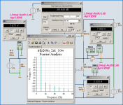
IRFP260N Class A output stage FINAL
IRFP260N Class A output stage FINAL
A final teaser for a few of my friends only.
As can be seen Class A output consumes 100 Watt.
This test today shows a 10V peak output across 5 Ohm.
This means 10 W-rms pure single end Class A. ( +10 dB on speakers )
The max output is closer to 20 Watt RMS ( 14 Volt peak )
IRFP260N has got a RDSon ~ 0.04 Ohm.
And is a TO247AC HEXFET rated 300 Watt.
After now finished output stage, I will now put all efforts
to finish My JFET input / voltage amplifier.
....... so it can match my power output circuit .......
Unfortunately, as mentioned in my previous post
I can not publish this project any more here at our / your Forum.
Who's most sorry for this, I really do not know.
It is me ... as usual ... or ...
Regards, my friends
Lineup
IRFP260N Class A output stage FINAL
A final teaser for a few of my friends only.
As can be seen Class A output consumes 100 Watt.
This test today shows a 10V peak output across 5 Ohm.
This means 10 W-rms pure single end Class A. ( +10 dB on speakers )
The max output is closer to 20 Watt RMS ( 14 Volt peak )
IRFP260N has got a RDSon ~ 0.04 Ohm.
And is a TO247AC HEXFET rated 300 Watt.
After now finished output stage, I will now put all efforts
to finish My JFET input / voltage amplifier.
....... so it can match my power output circuit
.......Unfortunately, as mentioned in my previous post
I can not publish this project any more here at our / your Forum.
Who's most sorry for this, I really do not know.
It is me ... as usual ... or ...
Regards, my friends
Lineup
Attachments
Re: IRFP260N Class A output stage FINAL
This is a totally irrelevant parameter in a class A stage. It's only important when the mosfet is saturated like in switching applications.lineup said:
IRFP260N has got a RDSon ~ 0.04 Ohm.
You haven't actually shown us anything so we probably don't know if we should miss anything.lineup said:
Unfortunately, as mentioned in my previous post
I can not publish this project any more here at our / your Forum.
Who's most sorry for this, I really do not know.
It is me ... as usual ... or ...
- Status
- This old topic is closed. If you want to reopen this topic, contact a moderator using the "Report Post" button.
- Home
- Amplifiers
- Solid State
- Otopia Project - new idea amp