i suggest to add emitter degeneration resistors at the input diff. stage
(the value of resister is about 100R ~ 300R)
it improve its linearity and dynamic range and TIM performance.
the position of emitter degeneration resistors is inserting into the emitter of two 2sa872 and the 100r SVR.
(the value of resister is about 100R ~ 300R)
it improve its linearity and dynamic range and TIM performance.
the position of emitter degeneration resistors is inserting into the emitter of two 2sa872 and the 100r SVR.
a current source for the diff amp, and one for the VAS load would be a couple of improvements i can think of.
actually, build the amp as-is, but using some output devices more readily available, such as IRF140 and IRF9140, and leave the 470k resistor in the diff amp, and the 15k resistor in the voltage amp stage, in places where you can easily replace them with other circuitry. then you can build current sources to put in place of the resistors and do some experimenting with the circuit.
actually, build the amp as-is, but using some output devices more readily available, such as IRF140 and IRF9140, and leave the 470k resistor in the diff amp, and the 15k resistor in the voltage amp stage, in places where you can easily replace them with other circuitry. then you can build current sources to put in place of the resistors and do some experimenting with the circuit.
Interesting resource for audio matched MOSFETs = http://aussieamplifiers.com/lateral.htm 
Thank you all for the feedback. I must admit that I would not be able to change or add anything to this circuit because I am a simple DIY handyman with expertise in some other fields.
I understand just a little in schematics. The reason I picked up this schematic is that it looked simple, looked similar to other amplifier designs, promised sufficient power and used MOSFET as output.
I would ask if those "expensive" MOSFETs in the output stage could be replaced with something more available and less costly.
Perhaps, this could grow in the beginner's Hi-Fi amplifier."
Thanks for all replies.
unclejed613 said:actually, build the amp as-is, but using some output devices more readily available, such as IRF140 and IRF9140
No don't do that. This design is not meant for those vertical MOSFET types and it will go into thermal runaway.
If you want to use cheaper and more easy to find output devices but still use MOSFETs there are plenty of designs out there that are properly thermally designed.
bokakob: FYI about those two separate 0.1 uF caps on the power rails across the output FETs = http://www.diyaudio.com/forums/showthread.php?postid=1228034#post1228034 ... make 'em be plastic caps = covers a world of power supply sins ...
Hi,
alternative FETs are renesas 2sk1056/j160, 2sk1057/j161, 2sk1058/j162, or Exicon ec10n16/p16, ec10n20/p20 or magnatec buz900p/905p, buz900d/905d, buz900/905. These and any other lateral FETs are suitable.
The second stage transistor (VAS) is driving the output FETs directly. I would suggest that you do not parallel output devices to cope with a lower value load. Stick to 8ohm speakers not 6ohm, not 4ohm and not 4 to 8ohm.
The only stability enhancing components I can see are the decoupling caps and the output Zobel. You may have to fit some additional trimming components to ensure stability into reactive loads. You will need an oscilloscope to identify if any additional components are needed and if those fitted do the job adequately.
Arlo's emitter degen are already fitted. The 100r pot achieves the same end and is equivalent to 50r on each emitter. An emitter resistor on the VAS may help.
Did you take this one any further, Bob?
Whilst truffling around the archives here, I found this design, which is based on the famous Hitachi apps one, but incorporates some of the suggestions made in this thread to improve stability: http://novagraph.com/examples/mosfet.html
It also has a Current Mirror.
The Exicon mosfets suggested by Andrew make perfect Hitachi replacements and I would question whether the Hitachi would win out over the Exicon in blind listening (assuming all things are equal).
Justin
richie00boy said:It is reasonable for a first project, but those MOSFETs are expensive and not so easy to find.
i would say barely reasonable, but a few very simple improvements will get it there. The MOSFETs are hard to find because they have been out of production for some 20 years or so. Fortunately, the direct replacements (although in a different case - not a problem if building an amp from scratch) are 2SK1058 and 2SJ162.
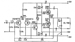
Arlo said:i suggest to add emitter degeneration resistors at the input diff. stage (the value of resister is about 100R ~ 300R)
Have a better look. There is avariable resistor between the emitters of the input stage - a variable resistor, last time i looked, was still a resistor. In effect this will be a 50 ohm resistance in each emitter leg (give or take 10-20 ohms due to adjustment needed for balance, but still enough).
unclejed613 said:actually, build the amp as-is, but using some output devices more readily available, such as IRF140 and IRF9140
Let me be blunt here: please don't post if you don't know what it is you are actually proposing. This has been mentioned countless times here, and IMHO whoever suggests replacing lateral MOSFETs with verticals next, shuld be banned. For the umpteenth time: TJHIS WILL NONT WORK, and worse, THE REPLACEMENT MOSFETS WILL GO INTO THERMAL RUNAWAy AND DESTROY THEMSELVES and probably cause untold anguish to the guy who is just trying to get into this amp DIY thing.
maxpou said:Hi, you can replace trimmer bias by transistor bias and put this transistor on the heatsink with output mosfet if you use a vertical mosfet. Maxpou
Sure, you can, and have an underperforming or nonfunctioning amplifier. Maxpow should read what I wrote to the last person i quoted. Lateral MOSFETs as the ones used in this schematic, do not require temperature compensation for idle cuurrents above about 80mA, which is the setting that should be used. A bias circuit as proposed above will provide compensation that is not needed, hence will just make things worse, and more complicated. PLEASE look at the schematics and know your parts before posting off-hand suggestions.
Now, here are some useful and REAL suggestions:
1) The 470k resistor in the emitter circuit of the two input transistors is a typo - it should be 47k.
2) The 15k resistor in the collector circuit of the 2SC1775 is asking for trouble as the amp will clip very asymetrically, and may also exhibit a phenomenon known as rail sticking. There is a simple modification that will fix that, it entails one additional resistor, diode and capacitor, and goes like this:
- instead of single 15k resistor, use two resistors in series, 5.6 to 6.8k each. Connect the ends of this series combo where the original 15k resistor is in the schematic diagram.
- Use an electrolytic cap of 47 to 100uF/50V, connecting it to the midpoint of the above two series connected resistors (+ terminal of cap) to the output (- terminal of cap)
- Use one diode type 1N4002,3,4,5,6 or 7, connect anode to the midpoint of the above two series resistors, and cathode to the + supply rail of the whole amp.
This will give youi a simple, but sound amp to play with...
ilimzn said:
Fortunately, the direct replacements (although in a different case - not a problem if building an amp from scratch) are 2SK1058 and 2SJ162.
actually, the TO-3P case fits very nicely in place of a TO-3, as long as you keep the emitter and base leads in their proper order. connecting the collector may sometimes present a bit of a conundrum, depending on the actual transistor tab and heat sink layout, but it can be done, if all else fails, with a piece of 16ga wire soldered from the collector lead to the pc board, or to a lug on the mounting screw.
some of the newer TO-3P packages are slightly longer than the original ones (from the mounting hole to the E-B leads), even though the E-B lead spacing is identical, and may be a bit difficult to retrofit in place of a TO-3.
i have some transistors with the original TO-3P package (TIP-147's), and the package is not only the right size for retrofitting, but the tab is triangular. i also have some IRFP240/9240's here that would be an easy retrofit as long as an angled case isn't a problem. but the larger flat pack transistors (i'm looking at an MJL3281) won't retrofit without enlarging the B-E holes in the heat sink.
unclejed613 said:actually, the TO-3P case fits very nicely in place of a TO-3
Yes, hence the name TO3P vs original TO3. i doubt the person that started the thread has already a pre-made PCB or heatsink for TO3 so he should not have a problem anyway.
I also have some IRFP240/9240's here that would be an easy retrofit as long as an angled case isn't a problem.
Are you selectively reading on purpose or you really want to get into trouble with the moderators? STOP SUGGESTING UNSUITABLE REPLACEMENTS!!!
Let me repeat myself, so you can read this again:
This has been mentioned countless times here, and IMHO whoever suggests replacing lateral MOSFETs with verticals next, shuld be banned. For the umpteenth time: TJHIS WILL NONT WORK, and worse, THE REPLACEMENT MOSFETS WILL GO INTO THERMAL RUNAWAy AND DESTROY THEMSELVES
And yes, in case you were wondering, I meant YOU. IRF parts do not replace 2SJ/2SK laterals, unless considerable other modifications are made, period. In this particular schematic they will not be able to be biassed correctly, and will fail with a gate puncthrough the first time the amp clips.
Hello,
I don't want to look stupid, but how would the IRF go burnt so easily as they have a SOA which is MUCH bigger than the SK/SJ. I don't understand this statement about thermal runaway of the IRF and not the SJ/SK. If the bias is adjusted, I don't see where the problem could be as long as the heatsink is big enough (it's true with every mosfet anyway). Nelson Pass uses them extensively with only a tiny bipolar for a protection. The main problem with these IRF would be with going into self oscillation I guess. Maybe a lot of people had problems with the IRF blowing up, but I'm not so sure. They are known to be very rugged and used in applications handling way more power than an amplifier. Can someone report stories about it, I would be interested.
I personnaly used IRF540/9540 in a 70W amplifier and nothing went wrong. For bias, I used a Vbe multiplier stuck to the heatsink, nothing fancy.
Sorry for that statement, don't go angry at me please.
But I would like to have some proofs since I tend to like these IRF for there high S compared to the Hitachis.
Thank you
Hi,darian said:I personnaly used IRF540/9540 in a 70W amplifier and nothing went wrong. For bias, I used a Vbe multiplier stuck to the heatsink, nothing fancy.
it took me decades to get my head around the difference between lateral FETs and vertical FETs, enhancement mode and depletion mode?
They are so different from each other that they MUST be operated differently.
You have used a temperature compensated Vbe multiplier to correct for the decreasing Vgs as Tj temperature rises. Just the same way that BJTs need temp comp.
People that should know better and those that don't know, suggest that for economy, the cheap verticals be substituted for the expensive laterals into a circuit that is not suitable for both types.
darian said:Hello,
I don't want to look stupid, but how would the IRF go burnt so easily as they have a SOA which is MUCH bigger than the SK/SJ. I don't understand this statement about thermal runaway of the IRF and not the SJ/SK. If the bias is adjusted, I don't see where the problem could be as long as the heatsink is big enough (it's true with every mosfet anyway). Nelson Pass uses them extensively with only a tiny bipolar for a protection.
Asking questions in general makes no-one look stupid. NOT asking them when you should, does - so you are doing well.
i will answer your first question last, first I will mention that Nelson's amos do not enter into this equation because of the way they are topologically made up. The bias current in them is actually set by a current source, so remains pretty much constant regardless of temperature. Note that this is not the case with the amp we are discussing here in this thread.
SOA is also not a direct concern. Every MOSFET will die if the SOA is broken. It may not occur in the given circuit becausse something else may give out first, but when you are given only a part of the complete amp (missing power supply, protections, etc), you have to think worst case.
For the following discussion, it would be good if you can pull up a HEXFET datasheet, say for an IRF640. Look at the graph showing Vgs versus Id, there are usually 3 curves, one per operating temperature. If you look at a constant Vgs value, and where it intersects the varius temperature curves, you will see that with a fixed Vgs, as the temperature rises, so does Id, and quite a bit too.
As passing a current through a MOSFET with some Vds over it means the MOSFET heats up, if the Vgs is held constant, with constant Vds, Id will rise on it's own - how fast depends on starting point and heatsink size.
It is completely unacceptable to regulate this by adjusting heatsink size. You may end up with a completely impractical heatsink and/or final idle current - and you may even have a situation where the SOA is crossed before you do get to a stable point.
You will also notice that in the diagram, the three curves for very different temperatures, eventually intersect. At this point the temperature coefficient becomes negative, so this is the point the MOSFET will naturaly tend to stabilize at. Now look at what current this happens - usually very close to the maximum alowable. Not accedptable at all. Obviously we have to use some form of bias compensation.
Now, find the datasheet for the 2SK1058. This same point occurs at Id~100mA, perfectly suitable as regular bias. hence, no further bias ciompensation is necessary.
The main problem with these IRF would be with going into self oscillation I guess. Maybe a lot of people had problems with the IRF blowing up, but I'm not so sure.
This can also be a problem with lateral MOSFETs, see 470 ohm resistors in the gates in the schematic at the start of the thread.
I personnaly used IRF540/9540 in a 70W amplifier and nothing went wrong. For bias, I used a Vbe multiplier stuck to the heatsink, nothing fancy.
Due to the emphasized text, nothing went wrong
") If you sued a simple resistor, it would have.
If you sued a simple resistor, it would have. I would like to have some proofs since I tend to like these IRF for there high S compared to the Hitachis.
High S is nice to have, but it does not come free. The capacitances are higher, and it can be less linear 9although it's not linear anyway so...). Keep in mind the laterals are the very first power MOSFETs designed, so they are OLD technology. their biggest virtue is that they were purposefully made as complementaries (which actually makes the P and N types very different internally). With IRF parts it takes a bit more work to figure out what ones are reasonably complementary.
Edit: one more thing i forgot to mention - laterals have integrated gate protection zeners, hexfets do not. Consider what it means in the context of the amplifier schematic from the start of the thread - emember that gates do not draw current like bipolars, and what will happen with the gate to source voltages when the amp clips?
- Status
- This old topic is closed. If you want to reopen this topic, contact a moderator using the "Report Post" button.
- Home
- Amplifiers
- Solid State
- Simple MOSFET amp