Hi
I have an idea...
Could the circuit attached work as a FM demodulator?
Constant width of output pulses on every zero crossing with varying cycle time, plus output filtering.
If yes, anyone sees any sources of distortion in it?
Waiting for comments
regards
Adam
I have an idea...
Could the circuit attached work as a FM demodulator?
Constant width of output pulses on every zero crossing with varying cycle time, plus output filtering.
If yes, anyone sees any sources of distortion in it?
Waiting for comments
regards
Adam
Attachments
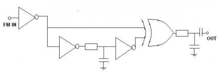
Coincidence demod works like generating costant-width pulses on FM zero crossing??
Yes, you are actually converting the FM signal into a PWM signal that is then demodulated by a lowpass filter.
Regards
Charles
darkfenriz said:Hi
I have an idea...
Could the circuit attached work as a FM demodulator?
Constant width of output pulses on every zero crossing with varying cycle time, plus output filtering.
If yes, anyone sees any sources of distortion in it?
Waiting for comments
regards
Adam
Yes; here is a slightly fancier one I designed earlier. I designed and built these as part of a system for the government and there are about 8 realisations of the circuit attached currently demodulating radio telemetered seismic signals for nearly all of South Australia’s analogue seismic recorders.
It demodulates an FM signal with a carrier of 1.5kHz, modulated +/-500Hz. For practically zero drift, a digital counter clocked by a 20MHz oscillator is implemented as the monostable. This provides an accurate pulse of 204.8uS. HCMOS (rail-rail output) gates are used and the +5V logic supply is tightly regulated. For low output ripple, the PWM output is demodulated with a 100Hz 6 pole Butterworth low pass filter. This filter effectively sets the bandwidth of the demodulator.
Oh, and to keep this thread on topic, here is an arbitrarily selected audio amplifier related link:
http://www.dself.dsl.pipex.com/ampins/pseudo/subjectv.htm
Cheers,
Glen
Attachments
Thank you guys
I actually thought it is more like pulse frequency modulation, rather than PWM before the output filter, but never mind.
Glen, it is hard to read your schematic for me, do you have a higher resolution version?
NOW!! If I feed the input with a pure square clock and swap the capacitor between inverters with a condenser microphone, will I get a mic preamp? What do you think?
regards
Adam
In the audio literature, you will find this called a "pulse count demodulator". since there is a constant width pulse generated for every zero crossing of the IF signal, and the IF frequency is continuously varying in proportion to the original audio modulation, you end up with a set of constant-width pulses whose density varies in proportion to the audio signal. (so it's not really "PWM"). You then low-pass filter it to recover the baseband audio.
Disadvantages include signal-to-noise ratio as the amplitude tends to be low after the LP filtering and must be gained back up. Ultimate amplitude is dependent on the voltage levels of the "logic" generating the pulses. Bigger pulses require higher voltage "logic", which then has poorer pulse shapes and thus introduce other issues.
A number of classic tuners by Kenwood, and perhaps others, used variations on this scheme. Somewhere in my files, I have a DIY article from an electronics hobby magazine (Popular Electronics?) from way back when showing how to build one of these out of Germanium transistors.
The advantage to the concept is that if you can closely control the height, shape, timing and pulse width of the output pulses over operating conditions, you can have an extremely linear demodulator.
darkfenriz said:Thank you guys
I actually thought it is more like pulse frequency modulation, rather than PWM before the output filter, but never mind.
Glen, it is hard to read your schematic for me, do you have a higher resolution version?
NOW!! If I feed the input with a pure square clock and swap the capacitor between inverters with a condenser microphone, will I get a mic preamp? What do you think?
regards
Adam
Well, it's not strictly 'true' PWM because the frequency isn't fixed, but in terms of it's demodulation it can be looked upon as a form of PWM.
The output voltage is simply equal to the average voltage of the pulse output. For instance, if the duty cycle is 50% and the pulse height is 5V, the output voltage is 2.5V.
Your mic amp idea would work, to a degree. I have a better schematic, but not on the computer I'm using now. If you still wan't it, you'll have to wait a couple of days.
Cheers,
Glen
Hi BrianL
---A number of classic tuners by Kenwood, and perhaps others, used variations on this scheme. Somewhere in my files, I have a DIY article from an electronics hobby magazine (Popular Electronics?) from way back when showing how to build one of these out of Germanium transistors.---
Probably Wireless World. Cyril Bateman told he made his first PCB's for a "Pulse Count Demodulator" which circuits of were publish in the magazine. I will be interested to read the DIY article if you have it scanned.
This could be the Practical Wireless circuit:
http://philsvalveradiosite.co.uk/philsvalveradiosite/pulsecountingfmreceiver_1.htm
I seem to remember Clive Sinclair having this type of thing in one of his creations.
http://philsvalveradiosite.co.uk/philsvalveradiosite/pulsecountingfmreceiver_1.htm
I seem to remember Clive Sinclair having this type of thing in one of his creations.
G.Kleinschmidt said:
Your mic amp idea would work, to a degree. I have a better schematic, but not on the computer I'm using now. If you still wan't it, you'll have to wait a couple of days.
I've been waiting...
- Status
- This old topic is closed. If you want to reopen this topic, contact a moderator using the "Report Post" button.
- Home
- Amplifiers
- Solid State
- FM demodulator ??